On the Dynamics of Tensegrity Bridges
Abstract
This paper describes the nonlinear dynamics of planar tensegrity bridges designed for minimal mass. The three-dimensional bridge benefits by the planar analysis in the most important manner relating to topology of material. We start with the minimal mass bridge, counting both structural mass and deck mass, and then derive the nonlinear dynamics to study dynamic behavior of the minimal mass bridge. Suggested design criteria include static and dynamic response. The minimal mass tensegrity has an optimal complexity (number of elements), and we show how the dynamic response influences the best choice of complexity, in comparison with the optimal complexity of the static design. The structures are first designed with minimal mass criteria, accounting for equilibrium and static stability conditions, and subsequently, we investigate the dynamics of such structures subject to constraints on displacements and loads perturbations. We employ an efficient approach to rigid body dynamics in matrix form, modified to include cable masses. We also show how to pass from the matrix to vector form of the dynamics. The equations of motion are derived analytically using Newtonian methods, and include damping and bar length constraints. Prestress of cables is added to tune stiffness. We show an application for artificial gravity space habitats.
Keywords
Bridges, Tensegrity structures, Dynamics, Vibrations, Form-finding, Minimum mass, Optimal complexity
Introduction
Tensegrity structures are stable networks of compressive members (rigid bodies, bars, or pipes) connected with a set of tensile member (cables or strings). The idea of using tensegrity structures for bridges is not new [1,2] but only recent contributions have shown their efficient use of mass [3,4]. Michell [5] derived the minimal mass frames made of only compressed and only tensioned members (i.e. tensegrity) for simply supported loads and torsional loads. This motivated the search for minimal mass structures for any loading conditions [6-8]. Bars and cables are particularly efficient to obtain, e.g., cable-stayed bridges or arch bridges that can carry dead loads, moving loads, wind, earthquakes. Stiffness requirements can modify the minimum mass design, but that is a good start. The parametric design [2,9,10] can be efficiently employed with the definition of few complexity parameters and aspect angles, allowing the optimization of the bridge as function of span, loads, restraints, and adopted materials. The proposed structural approach can also model moving bridges thanks to the cables that can be rolled or pulled to control the structural shape. Tensegrity statics has been studied in many works [7,11-13], and the minimal mass and optimization problem has been applied in many fields like: acoustics dos Santos, et al. [14-19], biomechanics [20-22], form finding [19,23-26], stability of Tbar tensegrity structures [27]. The simplest form of the tensegrity dynamics was obtained by Skelton [28], where a matrix form was introduced, devoid of transcendental functions. These equations characterize the dynamics of any class 1 tensegrity network (no bar-to-bar connections), whereas Lagrange multipliers were added to handle the constraints of class k tensegrity (k bars can be connected to a node by frictionless ball joints) in Cheong and Skeltonand Nagase and Skelton [29,30]. The vector form of any class k tensegrity including gravity loads and damping are given as well [31-33], but the matrix form is preferred here. The control problems of tensegrity structures include: Henrickson, et al. [34] to control the shape of airfoils; Masic and Skelton [35] studied the influence of the prestress on the dynamic behavior of tensegrity. The stiffness properties can be changed through the prestress [36-38]. Other noticeable works on applied control are [39-41]. The optimal choice of cables to sense or actuate can be determined from Li, et al. [42] that derives the optimal selection of sensors and actuators for any linearized system. Bridges have attracted the interest of Engineers throughout the history because they represent the attempt of men to overcome obstacles. These structures are used wherever there is a river, a canyon or any road. Bridges allow easier connections between two different points and faster connections between people. In this paper, we have studied many typologies of optimal mass bridges showing their dynamic response to loads and perturbations. We also compared several complexities of bridges with parametric design and we studied the most important problems regarding their behavior. Then, we developed a new design method that merges minimal mass and dynamic performance. We here show a study that merges the minimal mass design under static loads with the dynamics of such designed structures. The goal is to obtain dynamic behavior that satisfies other constraints such as vibrations, stiffness, and deformed configurations. The author's previous papers have shown the minimal mass bridges for two different parametric designs, the first [3] based on a prevailing superstructure, and the second [4] based on a prevailing substructure. We here study the dynamics of planar substructure tensegrity bridges of class 1 (i.e. bars are not attached to each other at any nodes) and 3D bridges of class 2. Those kinds of bridges are the minimal mass structures to carry vertical downwards loads along the deck. We here also study the vibration modes by perturbing the structures in static equilibrium, and we simulate the dynamics of such structures under moving loads. We enforce bar lengths constraints that keep constant bar lengths. Moreover, the dynamic formulation applies to any class 1 tensegrity structures with cable-to-cable nodes, free from bars. The dynamics for class 1 could be generalized to any class k tensegrity systems through the computation of the Lagrange multipliers as shown in Nagase and Skelton; Cheong and Skelton; Skelton [28-30]. The string mass is added, and the prestress is used for stiffness tuning. The efficiency of such approach is shown with numerical results that highlight the vibration properties of the minimal mass bridges. The remainder of the paper is organized as follows. Section 5 deals with the dynamic formulation of class 1 tensegrity bridges. The statics and the minimal mass design are presented in Sect. 6. The parametric bridge is defined in Sect. 4. Numerical results of the minimal mass designs and dynamic simulations are presented in Sect. 7. Conclusions and future work are offered in Sect. 8.
Parametric Tensegrity Bridge Model
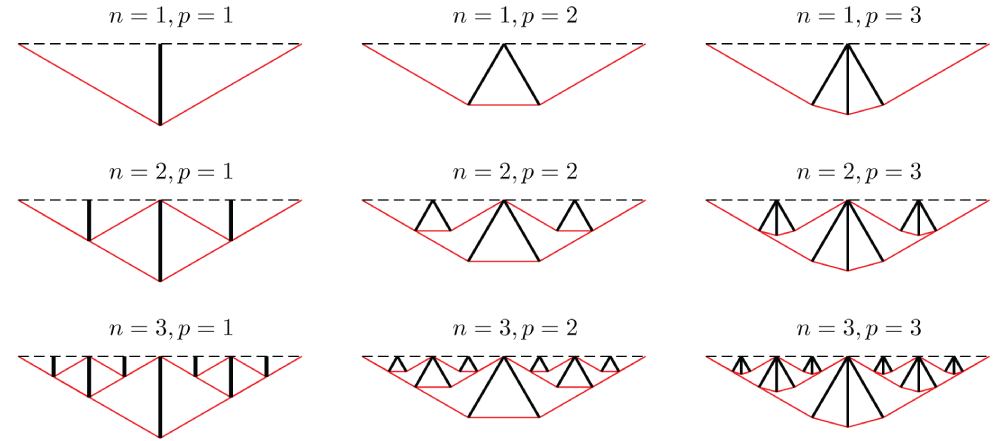
In this section, we describe the parameters that define the topology of the Tensegrity Bridge under study. It is possible to iteratively change those parameters to achieve optimal designs in terms of mass or dynamic properties. The planar bridge topology is considered here to elucidate the fundamental properties that are important in the vertical plane. We use the nomenclature from Carpentieri, et al. [4], referring to Figure 1 and Figure 2:
• a substructure bridge has no structure above the deck level;
• n denotes the number of self-similar iterations involved in the design;
• p denotes the number of bars in each substructure iteration;
• β is the aspect angle of the substructure measured from the horizontal.
For a tensegrity bridge with generic complexities n and p (Figure 1), the total number of nodes nn of each topology is given by
The number of bars nb and the number of cables ns are
We consider class 1 bridges (i.e. compressive members do not share common nodes, and p = 1) in which the supporting structure extend only behind the roadbed (i.e. substructure bridges, Figure 1) because Carpentieri, et al. [4] have shown that this topology ensures minimal mass designs. Each planar substructure bridge (Figure 1) is constrained with two fixed hinges at both ends with vertical reactions Ftot/2 and horizontal reactions wx. The planar module in Figure 1 can be replicated (along the direction out of the plane) to build three-dimensional structures able to carry vertical loads distributed on a horizontal plane.
Computation of deck forces
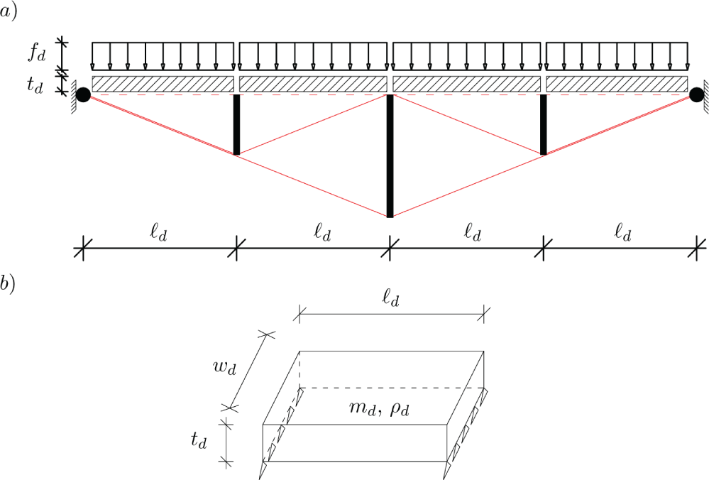
In this section we consider a distributed load along the span. Part of the load is the mass of the deck that must span the distance between adjacent support structures (complexity n will add 2n -1 supports).
The total load that the structure must support includes the mass of the deck, which increases with the distance that must be spanned between support points of the structure design (which is determined by the choice of complexity n ). We therefore consider bridges with increasing complexity n . The smallest n = 1 yields smallest structural mass and the largest deck mass. The required deck mass obviously approaches zero as the required deck span approaches zero, which occurs as
The deck, as illustrated in Figure 3, is composed by 2n simply supported beams connecting the nodes on the deck. Let the deck parameters be labeled as: mass md, mass density ρd, yielding strength σd, width wd, thickness td and length equal to:
The cross sectional of the deck beam has a moment of inertia equal to: . Each beam is assumed to be loaded by a uniformly distributed vertical load summing to the total value F and the total self weight of the deck (F) (g = 9.81 ms-2):
Assuming that the beam of a single deck section is simply supported between two consecutive nodes of the bridge, the maximum bending moment is equal to fd`2 d/8 and the maximum stress is given by Navier's equation [43]:
The thickness of the deck beam is:
Substituting (3), (4) and (6) into (5) we get the following equation for the mass of one deck section:
Where:
The total force acting on each internal node on the deck is then the sum of the force due to the external loads and the force due to the deck:
Dynamics of Class 1 Tensegrity Bridges
This section describes the general notation of tensegrity structures (Sect. 5.1) and the case of class 1 tensegrity (Sect. 5.2). Then, we derive the equations of motion for class 1 in matrix and vector form (Sect. 5.3). A simple but efficient algorithm for the bar lengths correction is presented (Sect. 5.4).
Basic notations
In the following we will indicate matrices with bold capital letters (i.e. X), vectors with bold lower case letters (i.e. x), while scalars are indicated with italic letters (i.e. x) Let now consider a tensegrity system composed of nn nodes, nb bars and ns cables. The following assumptions are used:
• bars are straight rigid bodies with uniform mass density, constant cross sectional, and negligible rotational inertia about their longitudinal axis; tubes or pipes can easily be included but we treat solid bars to simplify notation.
• cables are straight elastic members, that can only take tensile forces;
• bars and cables are connected with frictionless ball-joints eventually loaded with external forces at each node.
The ith node is located by the vector ni . By stacking nodal vectors, we obtain the following nodal matrix:
The vector of external forces acting on the ith node is wi , and the matrix of external forces is:
The vectors of the kth bar and cable are respectively bk and sk . For example, if the k bar connects nodes i and j, then bk = nj -ni. By stacking these vectors, we can obtain the following matrices of bars and cables:
Let us now define the connectivity matrices of bars and cables CB and CS . The general ith row of CB (or CS) corresponds to the ith bar (or cable), and the element CBij (or CSij) is equal to: -1 if vector bi (or si) is directed away from node jth, 1 if vector bi (or si) is directed toward node jth and 0 if vector bi (or si) does not touch node j. Then, for each tensegrity system, the following relationships yield:
The center of mass of the k bar between nodes i and j is located by the vector rk = (ni +nj)/2. Collecting all the rk vectors, we get the following matrix:
Let us define now the matrix CR , in which the ith row corresponds to the bar bi and the element CRij is equal to: 1/2 if vector bi is touching node j, or 0 if vector bi does not touch node j. Then, the following yields:
Let now consider a cable k with: Young modulus of the material Esk, cross sectional Ask, and rest length Lk. The force density is defined as:
Where: ksk = EskAsk/Lk, sk = ∥sk∥, and ck is a damping coefficient. All the force densities γk can be collected in a diagonal matrix:
Note that is an operator that produces a diagonal matrix with the components x1, x2, ....., xn of the vector x.
Class 1 tensegrity structures
Let now consider a tensegrity system in which 2nb nodes are connected to only one bar (class 1 tensegrity) and n0 nodes are pinned and connected to only cables. In this assumption, we have nn = 2nb + n0, and it is possible to stack the above defined matrices such that:
Where: is the identity matrix, and is the null matrix. Note also that, the nodal matrix (10) is ordered as [N1 N2 N0], where and contain the initial and final nodes connecting the bars respectively; and contains all the n0 pinned nodes at which only cables are connected.
Equations of motion
For any class 1 tensegrity system, the equations of motion can be written in the following matrix form in N coordinates:
Where: M is the mass matrix defined as:
and: is a diagonal matrix of the mass of each bar. The stiffness matrix K is given by:
where denotes the diagonal matrix of force density in bars, given by:
and: is a diagonal matrix of terms . Note that is an operator that keeps only the diagonal terms of the square matrix X and set to zero all the off-diagonal terms.
The equations of motion (20) have been integrated over time with a Runge-Kutta 4th order algorithm. It is worth noting that the above procedure accumulates numerical errors due to the approximation of function n at each time step. This leads to errors in length of the bars. A procedure to keep constant the bar lengths are described in the following section.
Bar lengths constraint and addition of cable masses
Let's call bk the vector of the kth bar. If lk is the original length, the error in length results:
In the spirit of constraint stabilization [30], we can drive the constraint error to zero by augmenting the following to the dynamic equations:
ωk are the natural frequencies of the bar length corrective function (to be chosen a priori). The above correction can be implemented in the dynamics described in the above section by correcting the bar force densities as:
Where: and , being ζk the damping of the bar length corrective function (also to be chosen a priori). We here show now how to include the mass of the cables in the dynamics (20). The following procedure allows adding the mass of the cables increasing the mass of the bars described in the above section. Then, the mass matrix can be modified as:
Where:
• is the mass of kth bar from node i and j;
• is the mass of the strings competing to bar k
and: , are the half of the mass of the strings attached to nodesiand j; nb,i, nb,j are the number of bars attached to nodesiand j (note that nb,I = nb,j = 1 for class 1 structures).
Statics and Minimal Mass Design
We obtain in this section the statics equations as a particular case of the dynamics. Then, we design the structure for minimal mass requiring that the static equilibrium is satisfied. The optimal designs are conducted under yielding and buckling constraints. In static conditions, we will have , and then the dynamics (20) reduces to:
The stiffness matrix in statics is also equal to:
Then (28) becomes:
Substituting (13) into (30):
Finally the statics equation is given in the form:
Note that in (32) is a unique function of for class 1 tensegrity, as highlighted in (23). The system of equations (32) is also valid for any class k tensegrity systems (in which more than one bar can converge in the joints) but the computation of the Lagrange multipliers is required as illustrated in literature [28-30].
Minimal mass design for class 1
Let's restrict to the special case of class 1 tensegrity in which: nb = β, ns = α, n = 2. In this case, the nodal, load and connectivity matrices can be rearranged such that:
Where: N1, N2, W1, W2 are 3×β matrices, I = Iβ is the identity matrix, and CS1, CS2 are α×β matrices. With the assumptions (34), the system (32) can be partitioned such that:
First of all, let's sum equations (35):
The ith columns of the system (36) is:
Applying the following rule: in (37), we have:
Stacking up all equations (38), we obtain:
Where:
All the solutions of (39), under the constraints γ ≥ 0 and if there exist, will be of the form:
Where: Γ+ denotes the Moore-Penrose pseudo inverse of Γ, and ζ ∈ ℝα is any vector. System (39) can be partitioned such that:
Where Γ1 contains all independent columns of Γ. Then, the solution γ1 will be unique in terms of γ2:
with the constraints: γ2 ≥ 0 and Γ1 > 0. Let's find now a solutions for the force densities in the bars. The ith column of the second system of equations in (35) is:
which can be solved as:
Stacking up all the columns (45) in a matrix form, we obtain the system:
where:
Finally, the minimal mass is achieved minimizing the function:
where:
• ρb and ρs are the mass densities per unit volume of bars and cables, respectively;
• σb and σs are the yielding or buckling stress of the bars and yielding stress of the cables, respectively;
•
•
Note that, for a class 1 structure, the solution λ in (46) is unique in term of γ.
Numerical Results
We here show numerical results on the minimal mass design (Sect. 7.1) and the dynamics (Sect. 7.2) of the substructure bridges presented in Sect. 4. We even show in Sect. 7.2.1 that the prestrain (i.e. the ratio between the unreformed length and stretched length of the cables) can be efficiently used to tune the stiffness of such bridges. Sect. 7.3 shows one possible extension of the proposed planar bridges to a 3D case. It is shown that such extension produces a class 2 tensegrity bridge (i.e. two bars can converge into a single node) that is able to carry out-of-plane actions due to wind or earthquakes. In all the examples, we assume mass density ρ = 7862 kg/m3, yielding strength σ = 6.9 × 10⁸ N/m2, and Young modulus E = 2.06 × 10¹¹ N/m2 for bars, cables and deck beams. We show the results for bridges with: complexity n ranging between 1 and 3, span L = 12 m, aspect angles β = 10 deg (2D bridges in Sects. 7.1, 7.2, 7.2.1), and β = 20 deg for the 3D bridge in Sect. 7.3, total external payload F= 12000 N, width of deck beams wd = 1.5 m. The bridges are constrained with perfect hinges (both vertical and horizontal displacements prevented) at the start (x = 0) and at the end (x = L).
Static design of substructure bridges
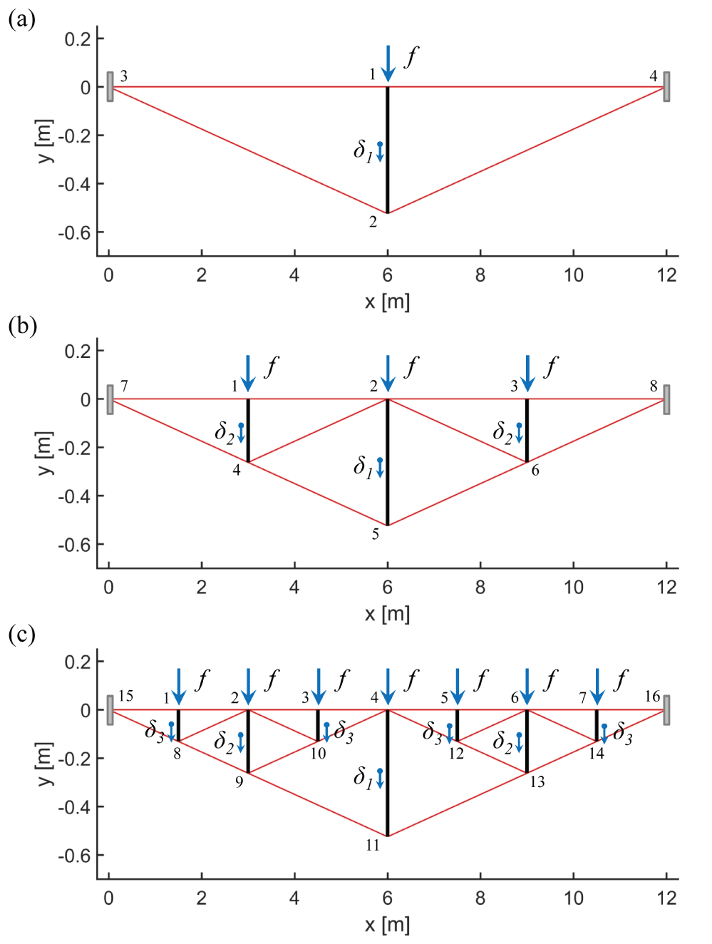
We design in this section the three bridges for n = 1 (Figure 4a), n = 2 (Figure 4b), and n = 3 (Figure 4c). Table 1 shows the main characteristics of the three different topologies (number of nodes (1), number of bars and cables (2)), and the value of the payloads computed with (9).
It is worth noting that the payload f = Ftot/2n decreases dramatically as complexity n increases. This is due to the increasing number of supports (in correspondence of each vertical bar) that are able to carry the load. For an infinite complexity n, we tend to a uniformly distributed load along the span of the bridge and the additional mass of the deck md in (7) is zero.
The static design has been performed assuming the members working at the yielding strength reduced with a safety factor 10. In a real design, such safety factor must be opportunely tuned to avoid yielding or buckling failures of the members during the dynamic motion under real loads (e.g. moving trucks, variable winds or earthquakes). The present paper has been instead focused on the study of the dynamic properties (mean angular frequencies) and the vibrations for changing complexities n and different kind of perturbations. Table 2, Table 3, and Table 4 show the results of the minimal mass designs of the three tensegrity bridges illustrated in Figure 4. In particular, we report the radii, rest lengths and elastic stiffness of each cable and radii and masses of the bars. The above quantities are obtained minimizing the mass function (49) over the force densities of the members (see Nagase and Skelton [30] for more detail on the minimal mass problem). Increasing complexity n from 1 to 3, generally brings to a reduction of the radii of bars and cables but the number of member significantly increases.
It is worth noting that the deck cables (i.e. the horizontal cables that connect each bar at the roadbed level) disappear for a pure minimal mass design for the choice of the external constraints (double fixed hinges). This would lead to a minimal mass design that, without the deck cables, is still in equilibrium under the vertical payloads on the deck but it is not in a stable configuration (any horizontal perturbation of the nodes on the deck would activate a mechanism). For such reason, we have picked a minimum radius of the deck cables equal to 10 mm for all the designs. We also consider the deck cables fully stretched (i.e. working at the yielding strength) in the static designs.
Dynamics of planar substructure bridges
Figure 4 shows the simulated planar substructure bridges. Initially, all the bridges are designed to carry the deck forces f exhibiting exactly the configurations illustrated in Figure 4. It is worth noting that, in such a static condition, the cables results prestressed of the required amount to carry the external loads. In particular, the deformed lengths can be obtained with the relationships in Sect. 4 and the geometry showed in Figure 4. The real rest lengths of the cables have been reported in Table 2, Table 3 and Table 4.
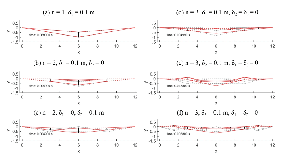
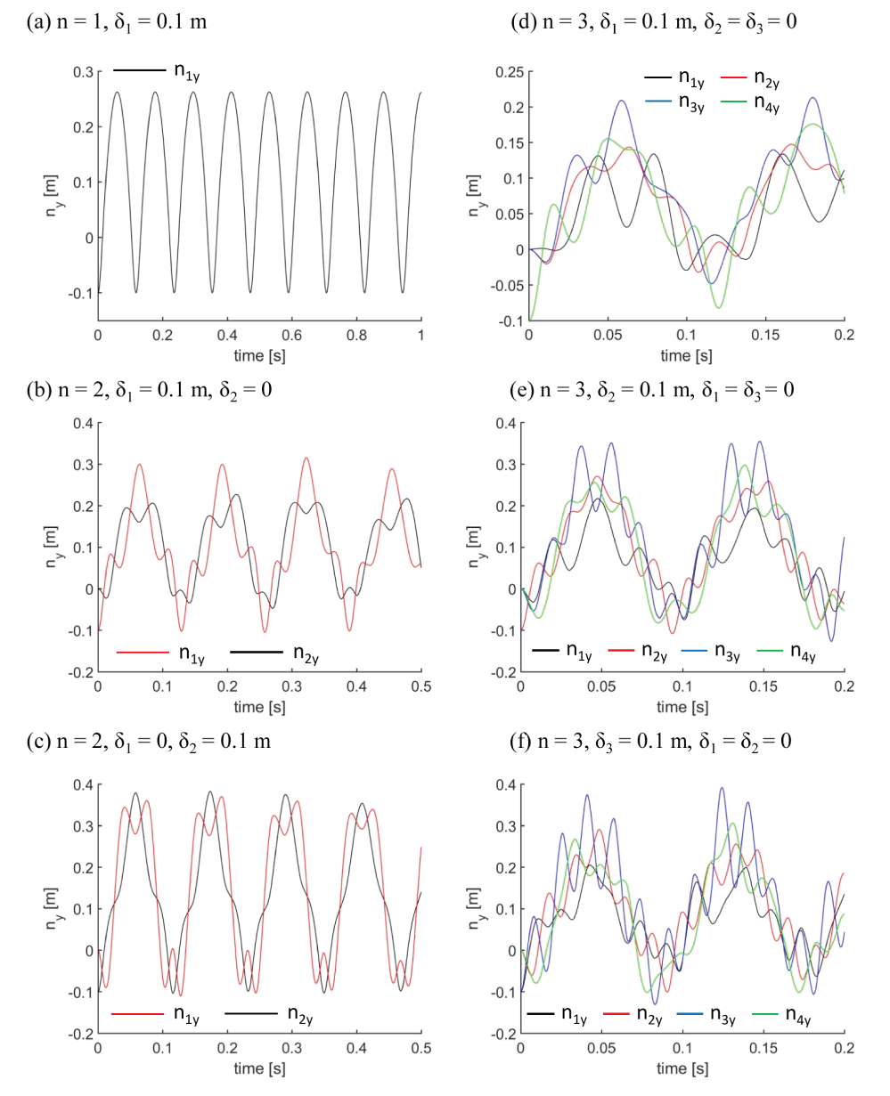
We have performed 6 dynamic simulations exciting the structures with an initial vertical displacement δ = 0.1 m to the bars. Alternatively, we have perturbed, for each simulation, bars of the same length with the same displacement δ. We did one simulation for the bridge with n = 1 (one bar) in Figure 4. The case n = 2 (three bars) in Figure 4, have been simulated fist moving the central bar and keeping the other two bars fixed, and then we have fixed the central bar and perturbed the remaining bars. Proceeding with the same spirit, we have performed three simulations for the case n = 3 in Figure 4. All simulations in this section do not include damping. Table 5 reports, at each line, the displacement assigned to the bars for each simulation and the mean angular frequencies measured numerically at the deck nodes of the structures.
Figure 5 contains significant snapshots of the deformed shape of the bridges during the simulations. In particular, Figure 6 shows the time histories of the vertical displacements (nz) of the node on the deck (i.e. all nodes with y = 0). From such charts we have numerically estimated the period of vibration T, the frequencies of vibration f = T-1 and the angular frequencies ω = 2πf (Table 5).
We have indicated in Figure 5 the slack cables with red dashed lines, and the initial configuration with black dashed lines. Table 5 shows that the angular frequencies increase with complexity n. In particular, for n = 1 we have a mean = 50.27 rad/s, indeed for n = 2 we obtained = 51.87 rad/s, and for n = 3 rad/s it raises to = 64.93 rad/s (see Table 5).
Stiffness calibration
The design of real bridges cannot be conducted only looking at statics as discussed in Sect. 7.1. One should check that the bridge doesn't deform more than some required values (usually decided by laws) under the external disturbances such as moving loads or wind. In other word, the bridge must have a minimum stiffness that prevents excessive displacements. In this section we show that the proposed bridges can be designed such that their stiffness satisfies any prescription could be imposed by law.
In particular, the prestrain is a typical way to control stiffness of tensegrity structures. For the proposed topology, moreover, it is sufficient to increase the prestrain of the deck strings to increase significantly the mean vertical stiffness of the structure. The tuning of the deck strings allows to keep the flat shape of the roadbed and minimize the mass (and then cost) required for the prestrain since not all the cables have to be stretched.
Table 6 shows the angular frequencies for 3 levels of prestrain of the deck cables (p1 = 0.99, p2 = 0.95, p3 = 0.9). Such frequencies have been computed numerically for the 6 simulations showed in Sect. 7.2. We can notice that, such small increases of the prestrain bring to very large increases of the angular frequencies that are proportionally related to the stiffness.
Extension to 3D case
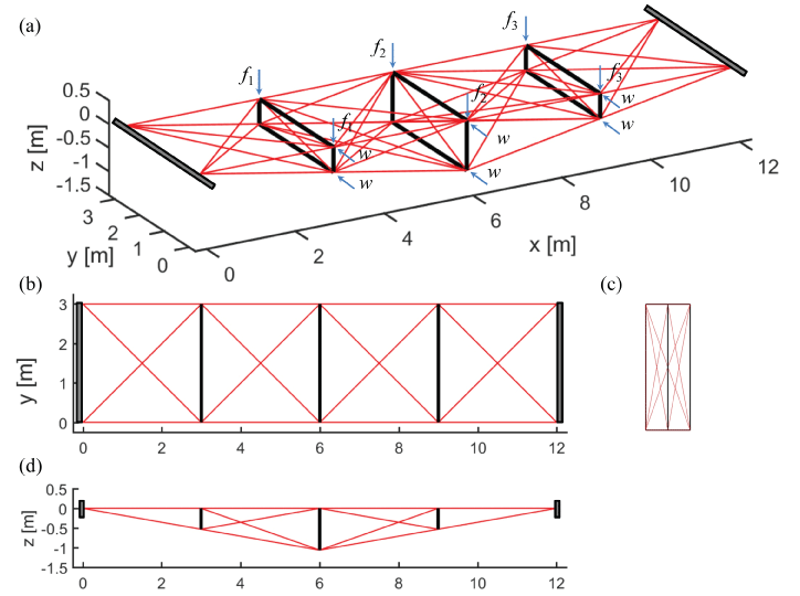
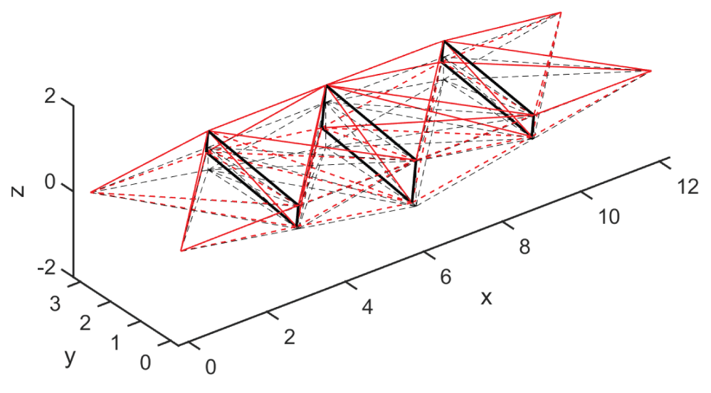
Let us consider now the 3D bridge in Figure 7. Such structure has been obtained coupling two planar tensegrity bridges of complexity n = 2 (Figure 4). The obtained structure has nn = 16, nb = 12, ns = 50. We have obtained a tensegrity structure of class 2 since the nodes are connected by two bars. In this condition, the dynamics presented in Sect. 5.3 slightly has to be changed to include the computation of the Lagrange multipliers. A detailed formulation of such kind of dynamics is out of the aims of the present paper and can be found in Skelton [28]; Cheong and Skelton [29]; Nagase and Skelton [30].
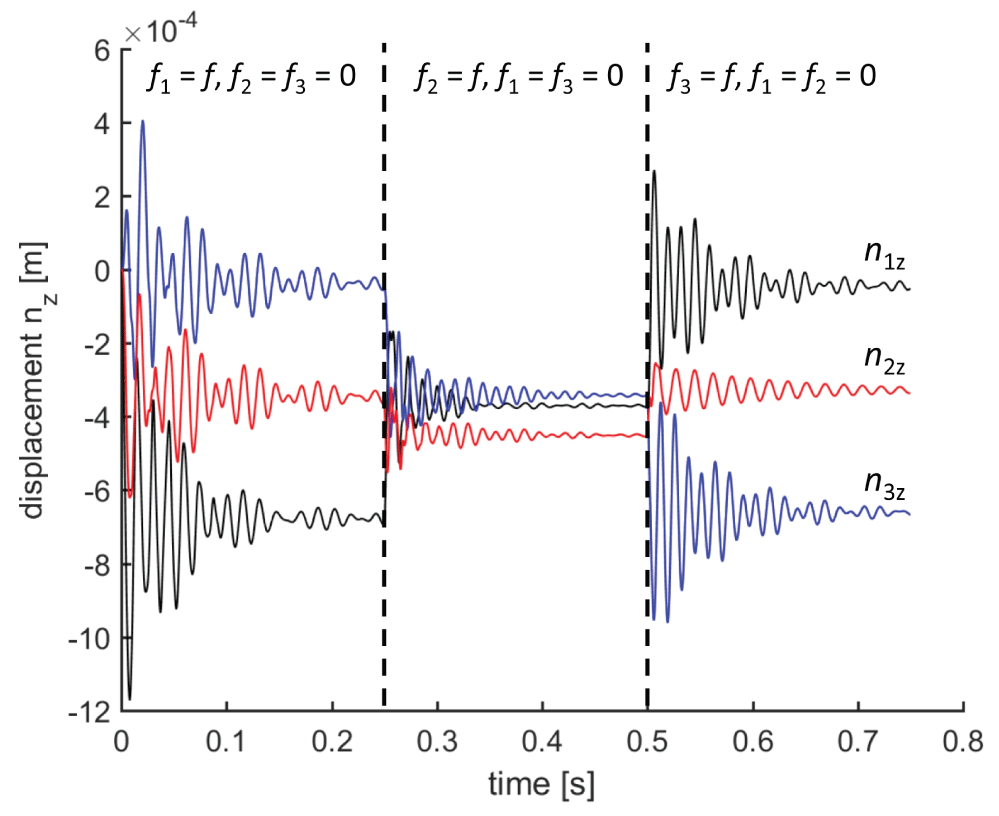
Two simulations of the 3D bridge have been performed: a first simulation under a vertical traveling load, and a second simulation under horizontal loads (due, for example, to wind). Both simulations include also a damping factor of ck = 25000 Ns/m. A first simulation of the 3D bridge was performed considering the bridge subject only to a traveling impulsive load f = 3701.44 N. In detail, the forces f1, ..., f3 on the deck have been set to:
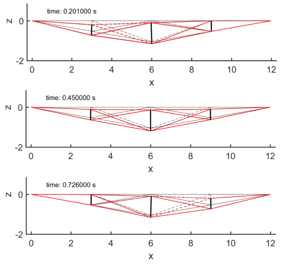
Figure 8 shows three significant snapshots of the 3D bridge for a traveling load. The three plots correspond to the deformed configurations of the bridge before the traveling load change position, proceeding rightward. It is worth to denote a remarkable vertical stiffness of the bridge from the displacements illustrated in Figure 9 (we have increased the displacements 300 times for visual clarity). The vertical displacements of the deck nodes are showed in Figure 9 and the damping have been calibrated such that the oscillation decades before the load changes position to the next point.
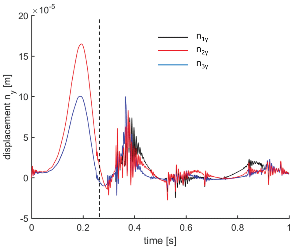
We have performed a second simulation of the 3D bridge in Figure 7 under horizontal impulsive loads of 250 N applied to the nodes with y = 0. The total load is then 1500 N. Such impulses have duration of 0.25 s and the total simulation time was set to 0.75 s. The deformed shape of the bridge at time t = 0.2 s is illustrated in Figure 10. The bridge shows rolling (or torsional) oscillations. Such kind of oscillations can be reduced changing the amount of prestrain as discussed in Sect. 7.2.1 or adding another layer of deck made of horizontal cross cables and bars. Figure 11 shows the horizontal displacements (with a rescaling factor 10 for visual clarity) of the deck nodes of the bridge under the horizontal loads. The vertical dashed line remarks the end of the impulsive loads. As easily predictable, the central node exhibits the bigger displacements.
Concluding Remarks and Future Work
We have studied the dynamics of tensegrity bridges with parametric topology and minimal mass properties. We have presented the dynamics of tensegrity structures (Sect. 5) for class 1 bridges. Such theory allows to solve in matrix or vector form the dynamics of rigid bars, enforcing the bar length constraint. The original formulation of the tensegrity dynamics has been modified to account for cable mass and elastic damping of the cables. An ad-hoc algorithm for the time integration with Runge-Kutta 4th order scheme has been employed in a MatLab® routine.
The topology of the proposed bridge is function of the number of the self-similar iterations (complexity n), the number of bars of each substructure iteration (complexity p), and the aspect angle below the horizontal roadway (angle β) (Sect. 4).
First of all, the bridges were designed under vertical loads due to the external loads and the deck mass. We were using the theory of minimal mass bridges given in Skelton, et al. [3]; Carpentieri, et al. [4] to design the bridges from n = 1,2 and 3, subject to buckling and yielding constraints, and with fixed-hinge/fixed-hinge boundary conditions (Sect. 6). The prestrain (i.e. the ratio between the stretched length and the rest lengths of the cables) has been used at different levels (from 0.9 to 0.99) to tune the vertical stiffness of the bridges.
We have employed the planar bridge module with complexity n = 2 to the design of a 3D bridge (Section 7.3). The dynamics of such bridge has shown the behavior under both vertical moving loads, and horizontal impulses.
We obtained smart designs of tensegrity bridges with optimal dynamic properties and designed with minimal mass strategies. This paper showed that the minimal mass design can be conveniently coupled with the dynamics to obtain designs featuring any desired behavior. The present approach can be successfully employed to design innovative structures like composite systems for civil engineering applications like tunnels, wells and domes.
The modern design approach that we have presented allows its application to several types of real bridge structures:
• Arch Bridges: they consist of one or more arch structures, pushing each horizontally at both side; they can allow an above or below deck level (respectively substructure or superstructure) ;
• Suspended Bridges: they typically consist of two compressive towers and a net of tensile cables in the longitudinal and vertical directions, that directly support the deck;
• Cable-Stayed Bridges: they work similarly to suspended bridges but in this case there is a system of inclined secondary cables that prestress the deck in compression.
• Beam Bridges: the main structure is made of one or more beams in bending, typically each beam is simply supported to allow rigid deformations (eg. in case of earthquake) without stresses;
• Truss Bridges: they are made of members in compression (struts) and in tension (tie) connected with ball joints, so each member is not in bending. The dynamics of tensegrity bridges will allow, as future work, further design constraints on stiffness issues (vibration frequencies, mode shapes, displacements for high winds conditions, etc). It is worth noting, however, that the capability all of these choices and adjustments are within the free parameters of the designs in this paper. The presented dynamics approach will evaluate the value (economics and performance tradeoffs) the use of feedback control for the deployable and service functions, or to adjust the stiffness of the structure (varying the prestress of the cables) to modify stiffness or damping after storm damage.
Future work will regard the analysis of general class k bridges (i.e. k bars terminate on at least one node). We also address to future work the control problem of such structures that can be achieved through the actuation of the cables. The cable control will lead also to deployable bridges, and the reduction of resonance phenomena.
References
- Bel Hadj Ali N, Rhode-Barbarigos L, Pascual Albi AA, et al. (2010) Design optimization and dynamic analysis of a tensegrity-based footbridge. Eng Struct 32: 3650-3659.
- Rhode-Barbarigos L, Ali NBH, Motro E, et al. (2010) Designing tensegrity modules for pedestrian bridges. Eng Struct 32: 1158-1167.
- Skelton RE, Fraternali F, Carpentieri G, et al. (2014) Minimum mass design of tensegrity bridges with parametric architecture and multiscale complexity. Mech Res Commun 58: 124-132.
- Carpentieri G, Skelton RE, FraternaliF (2015) Minimum mass and optimal complexity of planar tensegrity bridges. International Journal of Space Structures 30: 221-244.
- Michell AGM (1904) The limits of economy of material in frame-structures. Philos Mag 8: 589-597.
- Skelton RE, de Oliveira MC (2010) Optimal tensegrity structures in bending: the discrete Michell truss. J Franklin I 347: 257-283.
- Skelton RE (2009) Tensegrity Systems.
- Skelton RE, Nagase K (2012) Tensile tensegrity structures. Int J Space Struct 27.
- Sakamoto T, Ferr`e A, Kubo M (2008) From Control to Design: Parametric/Algorithmic Architecture. Actar, Barcelona, Newyork.
- Phocas MC, Kontovourkis O, Matheou M (2012) Kinetic hybrid structure development and simulation. Int J Archit Comput 10.
- Murakami H (2001) Static and dynamic analyses of tensegrity structures. Part II. Quasi-static analysis. Int J Solids Struct 38: 3615-3629.
- Pellegrino S (1990) Analysis of prestressed mechanisms. Int J Solids Struct 26: 1329-1350.
- Williamson D, Skelton RE, Han J (2003) Equilibrium conditions of a tensegrity structure. Int J Solids Struct 40: 6347-6367.
- Fraternali F, Senatore L, Daraio C (2012) Solitary waves on tensegrity lattices. J Mech Phys Solids 60: 1137-1144.
- Favata A, Micheletti A, Podio-Guidugli P, et al. (2016) Geometry and Self-stress of Single-Wall Carbon Nanotubes and Graphene via a Discrete Model Based on a 2nd-Generation REBO Potential. J Elasticity 125: 1-37.
- dos Santos FA, Rodrigues A, Micheletti A (2015) Design and experimental testing of an adaptive shape-morphing tensegrity structure, with frequency self-tuning capabilities, using shape-memory alloys. Smart Mat St 24: 105008.
- Fraternali F, Carpentieri G, Amendola A, et al. (2014) Multiscale tunability of solitary wave dynamics in tensegrity metamaterials.
- Xu GK, Li B, Feng XQ, et al. (2016) A Tensegrity Model of Cell Reorientation on Cyclically Stretched Substrates. Biophys J 111: 1478-1486.
- Zhang LY, Guang-Kui Xu (2015) Negative stiffness behaviors emerging in elastic instabilities of prismatic tenseg- rities under torsional loading. Int J Mech Sci 103: 189-198.
- Ingber DE (1998) The architecture of life. Sci Am 278: 48-57.
- Vera C, Skelton RE, Bossens F, et al. (2005) 3-D nanomechanics of an erythrocyte junctional complex in equibiaxial and anisotropic deformations. Ann Biomed Eng 33: 1387-1404.
- De Oliveira M, Vera C, Valdez P, et al. (2010) Nanomechanics of multiple units in the erythrocyte membrane skeletal network. Ann Biomed Eng 38: 2956-2967.
- Pellegrino S (1986) Mechanics of Kinematically Indeterminate Structures. University of Cambridge, England, U.K.
- Masic M, Skelton RE, Gill PE (2005) Algebraic tensegrity formfinding. Int J Solids Struct 42: 4833-4858.
- Motro R, Najari S, Jouanna P (1987) Static and dynamic analysis of tensegrity systems. Shell and Spatial Structures: Computational Aspects 26: 270-279.
- Micheletti A, Williams W (2007) A marching procedure for form-finding for tensegrity structures. J Mech Mat Struct 2: 857-882.
- Skelton RE, Montuori R, Pecoraro V (2016) Globally stable minimal mass compressive tensegrity struc- tures. Compos Struct 141: 346-354.
- Skelton RE (2005) Dynamics and control of tensegrity systems. In: IUTAM Symposium on Vibration Control of Nonlinear Mechanisms and Structures, Springer, Netherlands, 309-318.
- Cheong J, Skelton RE (2015) Nonminimal Dynamics of General Class k Tensegrity Systems. International Journal of Structural Stability and Dynamics 15.
- Nagase K, Skelton RE (2014) Minimal mass tensegrity structures. Journal of the International Association for Shell and Spatial Structures 55: 37-48.
- Sultan C, Corless M, Skelton RE (2002) Linear dynamics of tensegrity structures. Eng Struct 24: 671-685.
- Cheong J, Skelton RE, Cho Y (2014) A numerical algorithm for tensegrity dynamics with non-minimal coordinates. Mech Res Commun 58: 46-52.
- Josep M Mirats Tur, Sergi Hernandez Juan (2009) Tensegrity frameworks: Dynamic analysis review and open problems. Mechanism and Machine Theory 44: 1-18.
- Henrickson JV, Valasek J, Skelton RE (2015) Shape Control of Tensegrity Structures. AIAA SPACE 2015 Conference and Exposition, California.
- Masic M, Skelton RE (2006) Selection of prestress for optimal dynamic/control performance of tensegrity structures. Int J Solids Struct 43: 2110-2125.
- Tibert G (2002) Deployable tensegrity structures for space applications. Royal Institute of Technology.
- Calladine CR (1978) Buckminster Fuller's "tensegrity" structures and Clerk Maxwell's rules for the construction of stiff frames. Int J Solids Struct 14: 161-172.
- Guest S (2006) The stiffness of prestressed frameworks: a unifying approach. Int J Solids Struct 43: 842-854.
- Djouadi S, Motro R, Pons JC, et al. (1998) Active control of tensegrity systems. J Aerospace Eng 11.
- Bernard A, Smith IF (2007) Tensegrity active control: multiobjective approach. J Comput in Civil Engineering 21: 3-10.
- Narongsak K, Williamson D (2002) Modelling and control of class NSP tensegrity structures. International Journal of Control 75: 123-139.
- Li F, de Oliveira MC, Skelton RE (2008) Integrating Information Architecture and Control or Estimation Design. SICE Journal of Control, Measurement, and System Integration 1: 120-128.
- Gere JM, Timoshenko SP (1997) Mechanics of Materials. PWS Publishing Company.
Corresponding Author
Gerardo Carpentieri, Department of Aerospace Engineering, Texas A&M University, USA.
Copyright
© 2017 Carpentieri G, et al. This is an open-access article distributed under the terms of the Creative Commons Attribution License, which permits unrestricted use, distribution, and reproduction in any medium, provided the original author and source are credited.

