On the Dynamics and Computed Torque Control of an Asymmetric Four-Limb Parallel Schoenflies Motion Generator
Abstract
This paper deals with the dynamic analysis and control of a four-limb parallel Schoenflies-motion generator dedicating to fast pick-and-place operations, with an asymmetric topological architecture for saving mounting space. The concise equation of motion is built with principle of virtual work to characterize robot dynamics. Computed torque control is adopted to design the control scheme, of which the control variables are optimized by minimizing the errors of joint variables. Simulation tests are carried out along a trajectory of pick-and-place testing cycle to evaluate the control design and dynamic performances, which is verified experientially by observing the joint dynamics. The results show the effectiveness of the developed dynamic model and controller for the parallel robot under study.
Keywords
Schoenflies motion generator, Computed torque control, Parallel robot, Robot dynamics, Pick and place
Introduction
Parallel robots with three independent translations and one rotation around an axis of a fixed direction, a.k.a. SCARAa robots or Schoenflies motion generators (SMGs), dedicate to material handling in terms of pick-and-place (PnP) operations, thanks to their advantages of high speed/stiffness and lightweight architecture. For instance, the well-known Delta robot [1] that was commercialized by ABB Flexible Automation in the late 1990s, serving in three industry sectors, i.e., the food, pharmaceutical, and electronics industries. Amongst all types of the parallel SMGs, the robot counterparts with four identical RRПRb limbs in-parallel received the most attentions from both industry and academia. The research group "Laboratoire d'Informatique, de Robotique et de Microelectronique de Montpellier (LIRMM)" firstly developed the H4 [2] robot in two versions, with four identical limbs and an articulated traveling plate [3]. Later on, the similar versions of H4 robot, i.e., the I4 robot [4] and the symmetrical Par4 [5] were developed. The main difference among those robots lies in the different structures of articulated platforms [6]. The commercial version of Par4, namely, the Quattro robot by Adept Technologies Inc., hit the market in 2007, which is the fastest industrial PnP robot available. Besides, the LIRMM group proposed the Heli4 robot with a compact articulated traveling plate that is connected by a screw pair featuring full-circle end-effector rotation [7], of which the commercial version "Veloce. Robot" was developed by the Penta Robotics. Other four-limb parallel SMGs should be noticeable for their high performance [8-14].
aThe acronym "SCARA" stands for Selective Compliance Assembly Robot Arm or Selective Compliance Articulated Robot Arm.bR and П represent the revolute and П (parallelogram structure) joints, respectively, and an underlined letter indicates an actuated joint.
To authors' knowledge, most of the existing four-limb SMGs inherit the architecture of the Quattro robot with mobile platforms (MPs) of different architectures. On the other hand, these robots have a cylindrical workspace (WS) due to their fully symmetrical topological architecture, which is not optimum for the PnP operations that are normally distributed within a long and narrow space. From the perspective of the properties of PnP motions, the Ragnar robot [15] was designed with a rectangular workspace to utilize the shop-floor space efficiently, allowing more robots to be deployed side-by-side in shop-floors for utilization of spaces. However, this robot has limited end-effector rotation. By combining the advantages of the SMG counterparts, an asymmetric robot with Ragnar architecture and screw-pair based mobile platform (MP) was developed [16] as depicted in Figure 1, for efficient use of space with high rotational capability.
In general, the parallel PnP robots work in the domain of high frequencies with complex and coupled nonlinear dynamic models, which is a challenging task in their dynamic control. The major difficulty lies in finding a solution that not only can sufficiently describe the real robotic system, but also can possibly be calculated in real time for implementation into control algorithms [17]. Since the robot links usually do not have regular geometries, some assumptions will be made for simplification and computational efficiency [18-21], leading to simplified dynamic models but introducing modeling errors in turn [22,23], which calls for a highly advanced control algorithm to achieve a satisfactory dynamic performance. Computed-torque control (CTC) is well suited for trajectory tracking control when the dynamic model of a robot is accurately known [24]. Some illustrative examples of the application of CTC to parallel robots can be found in the literature [25-29]. If there are unmodeled errors unignorable, some adaptive CTC methods are able to capture the parameter variations [30-35]. For instance, the linear proportional-derivative (PD) parameters can be replaced with nonlinear ones with the elimination of the nonlinear factors such as the modeling error and the nonlinear friction [36]. If both structured and unstructured modeling errors exist, neural network CTC provides a better solution for robot control [37,38]. On the other hand, the controller enhancement may lead to the increased complexity and cost of design and implementation of the control schemes. In this work, CTC is applied to the dynamic control of presented robot under study, wherein the control variables are obtained by solving an optimization problem, aiming to achieve a tradeoff between the control precision and complexity.
In this paper, the dynamics of a four-limb fully parallel robot adapted for the PnP operations, towards the efficient utilization of shop-floor space, is investigated. A concise dynamic model for the robot under study is built with principle of virtual work. Computed torque controller is developed with the optimized control variables, which is numerically illustrated and evaluated experimentally. The comparisons show the effectiveness of the developed dynamic control strategy for the parallel robot.
Manipulator Architecture
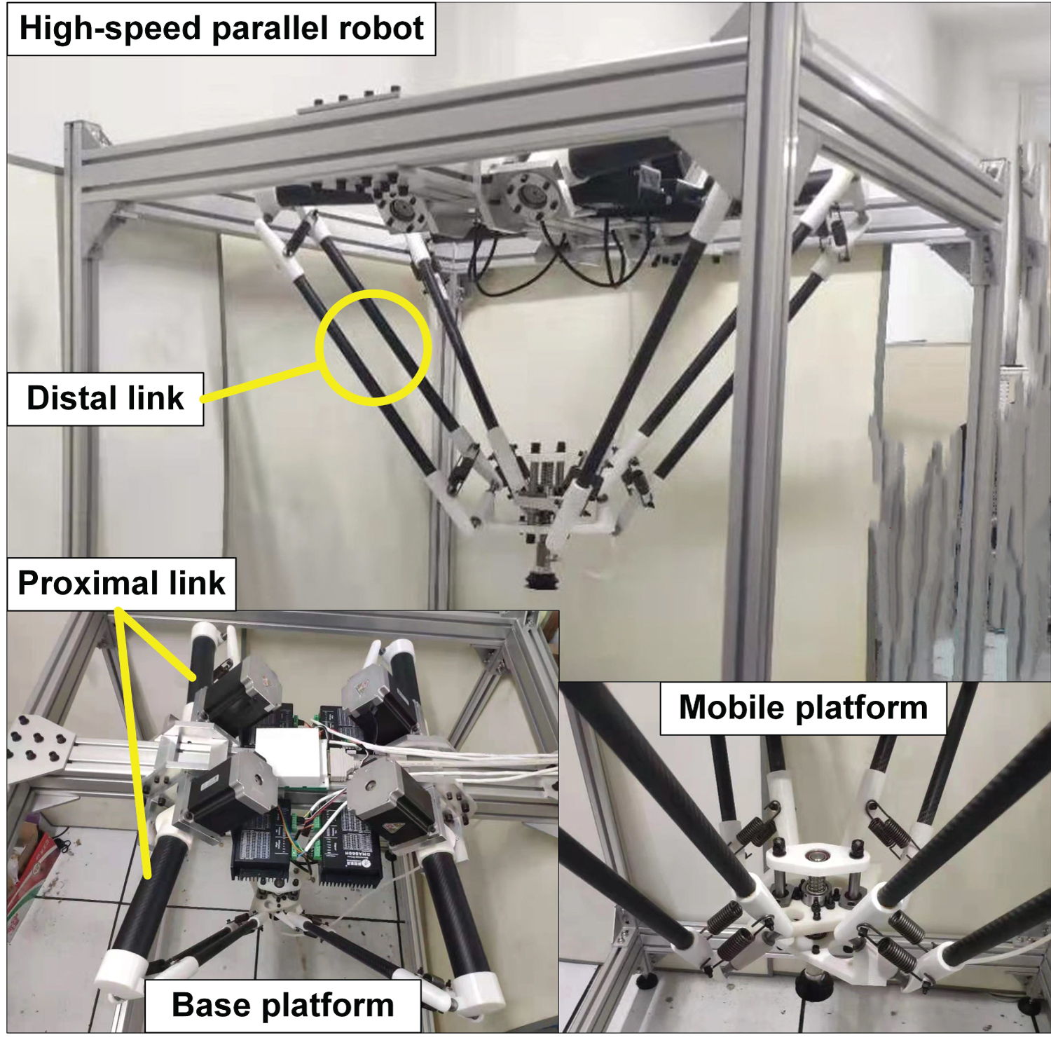
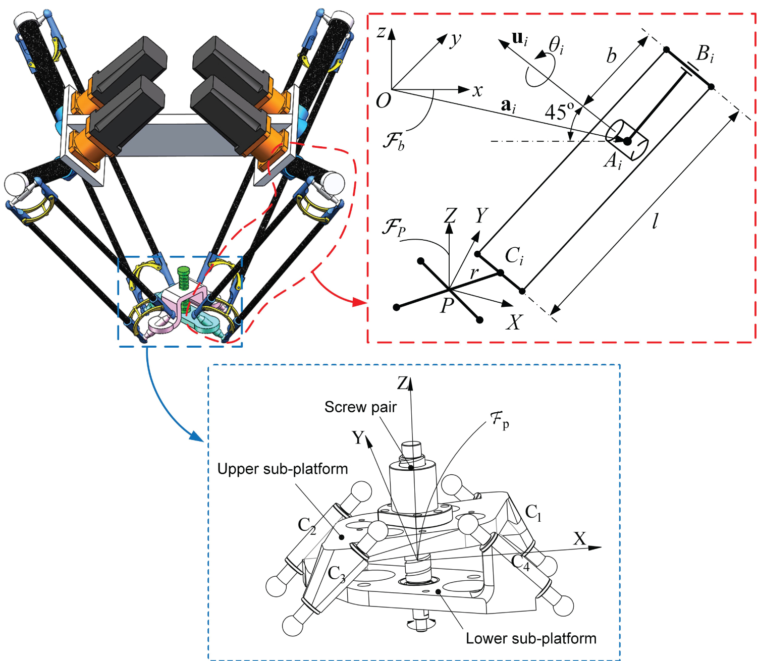
Figure 2 depicts the kinematic stricture of the robot with a screw-pair based mobile platform. Similar to its existing robot counterparts, each limb is composed of an actuated proximal link arm and a distal link to connect the base and mobile platforms. The mobile platform consists of two sub-platforms that are connected by a screw pair to transform the relative translation along vertical axis of two sub-platforms into rotational movement about the axis. For the lightweight design of the robot prototyping, as displayed in Figure 1, the proximal and distal link are fabricated with carbon fibre tubes, and most of the connecting components between the links and platforms are made of composite material by 3D printing. The previous work with a footprint ratio comparison [15] has revealed that the topological robot architecture under study determines a long and narrow workspace envelope well adapted to the PnP operations, with respect to (w.r.t.) the probability distribution of end-effector locations.
The reference coordinate frame Fb is built with the origin located at the geometric center of the base frame. The z-axis points upward, and x-axis is parallel to segment A1A2 between actuated joints 1 and 2. The moving coordinate frame Fp is located at geometric center of the lower platform, and the Z- and X-axis are parallel to z- and x-axis, respectively, in the neutral configuration. Point Ai represents the center of actuated joint, and Bi, Ci represent the center of short connecting bar at both ends of the parallelogram. The ith limb consists of an inner and an outer arms with link lengths b and l, respectively. The rotational capability can be enhanced by selecting an appropriate screw lead that is denoted by pitch h.
Kinematic Geometry and Jacobian Matrices
The robot's kinematic problem of this family has been extensively studied [39], which will be revisited by skipping the details. Let i, j and k stand for the unit vectors of x-, y- and z-axis, respectively, the axis of rotation of the ith actuated joint is denoted by and the Cartesian coordinates of points Ai, Bi and Ci, i = 1, ...., 4, are expressed in the reference frame asc
csgn (.) stands for the sign function of (.), and mod ( ) stands for the modulo operation.
where and represent MP position and orientation, respectively, and .
The robot's MP posture can be represented by .
By making use of the geometric constraint equation below:
the solutions to the inverse geometry problem of the robot can be solved as
with
For a given pose of the robot end-effector, each limb can have two postures that are characterized by the sign "-/+" in Eq. (3), which means that the robot can have up to 16 working modes (WMs). To avoid the mechanical collision, the working mode "- -+ +" is selected for the robot.
Kinematic Jacobian matrix of the robot
Differentiating Eq. (2) w.r.t. time yields
with
where Jx and Jθ are the forward and inverse Jacobians, respectively, and
As long as the forward kinematic Jacobian is nonsingular, the kinematic Jacobian matrix is obtained as
Jacobian matrices of the sub-platforms
Due to that the mobile platform consists of two sub-platforms, the upper sub-platform can translate in vertical direction with respect to the lower one, which introduces different velocities between the end-effector and sub-platforms. Besides, the Jacobian matrix between the upper platform and the actuated joints is also different from that of the lower one.
The velocities of the upper and lower sub-platforms, i.e., and , respectively, can be expressed as
henceforce, the Jacobian matrices mapping the velocities of the upper and lower sub-platforms and actuated joint rates are written as
or
with
where
Dynamic Modeling by Principle of Virtual Work
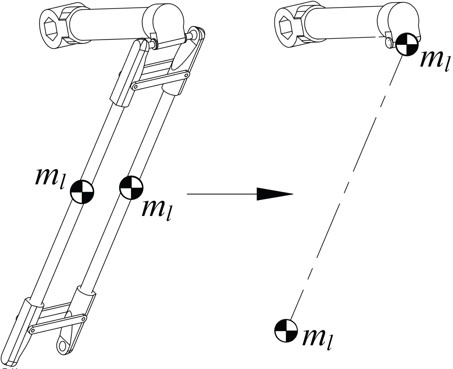
The main approaches for robot dynamic modeling usually include the Lagrangian formulation [40,41], the Newton-Euler equations [42] and the principle of virtual work [43]. Since the kinematic mapping of the movements between the input and output components of the robot linkage in the reference frame has been built in previous section and the links are simply connected, the relationship between actuation torques and inertia forces can be directly determined. Henceforth, the principle of virtual work is adopted to model robot dynamics for computational efficiency, without the operations of the differentiation on the system energy in Lagrangian formulation or recursive matrix propagation by Newton-Euler equations. Prior to modeling, it is supposed that the centers of mass of the links are located at their geometric centers, and the torques caused by the rotation of the outer arms are ignored due to the lightweight structure. The mass of each outer arm is simplified as two lumped masses located at the two ends of the distal link, as shown in Figure 3.
According to the principle of virtual work, the sum of the work done by the external and internal forces should to be zero. The external forces include actuating torque exerted on the actuated joints, and the gravities Gb, Gpu and Gpl of the inner arm, upper platform and lower sub-platforms. On the other hand, let fb, fpu and fpl be the inertia forces of inner arm and subplatforms, proportional to the internal forces, consequently, the equation of dynamics can be formed as
Where and represent virtual displacement of actuated joints and sub-platforms, respectively. Let g be the gravity coefficient, one obtains
with
where mb, ml, mpu and mpl are the masses of the proximal and distal links, upper and lower sub-platforms, respectively.
Differentiating Eq. (11) w.r.t. time leads to
Analog to the time-differential equations of motion, the small-amplitude displacements and of the upper and lower sub-platforms can be deduced as following
Combining Eqs. (14)-(18), Eq. (14) can be rewritten as
For any virtual displacement Eq. (19) should meet
After rearranging the Eq. (20) in connection with Eq. (17), the simplified dynamic model is derived as below:
With
Dynamic model (21) has been evaluated [44], applicable for the characterization of the robot dynamics, calculation of torques for selection of actuators and gearboxes, robot control, etc.
Control Scheme Design
Dynamic control plays an important role in the robot applications, thus, dynamic model (21) will be integrated in the controller for the robot. It is noteworthy that Eq. (21) does not take the frictions and other disturbances into account, namely, unmodeled errors, which may decrease the control precision. In light of this, the dynamic model is reformed as below
where f (θ, t) characterizes the unmodeled errors in terms of the frictions and time-varying stochastic disturbances, and here we let .
Amongst various control approaches for the robotic manipulators, computed torque control that is easily understood and of good performances, is an effective motion control strategy for robotic systems [45], which will be adopted to design the control scheme. According, the proportional-derivative (PD) control law is designed below
With
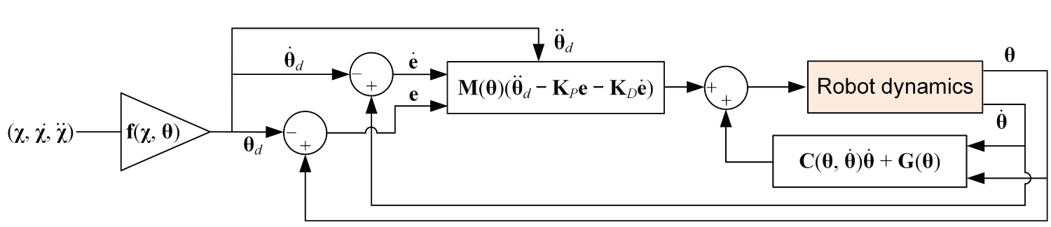
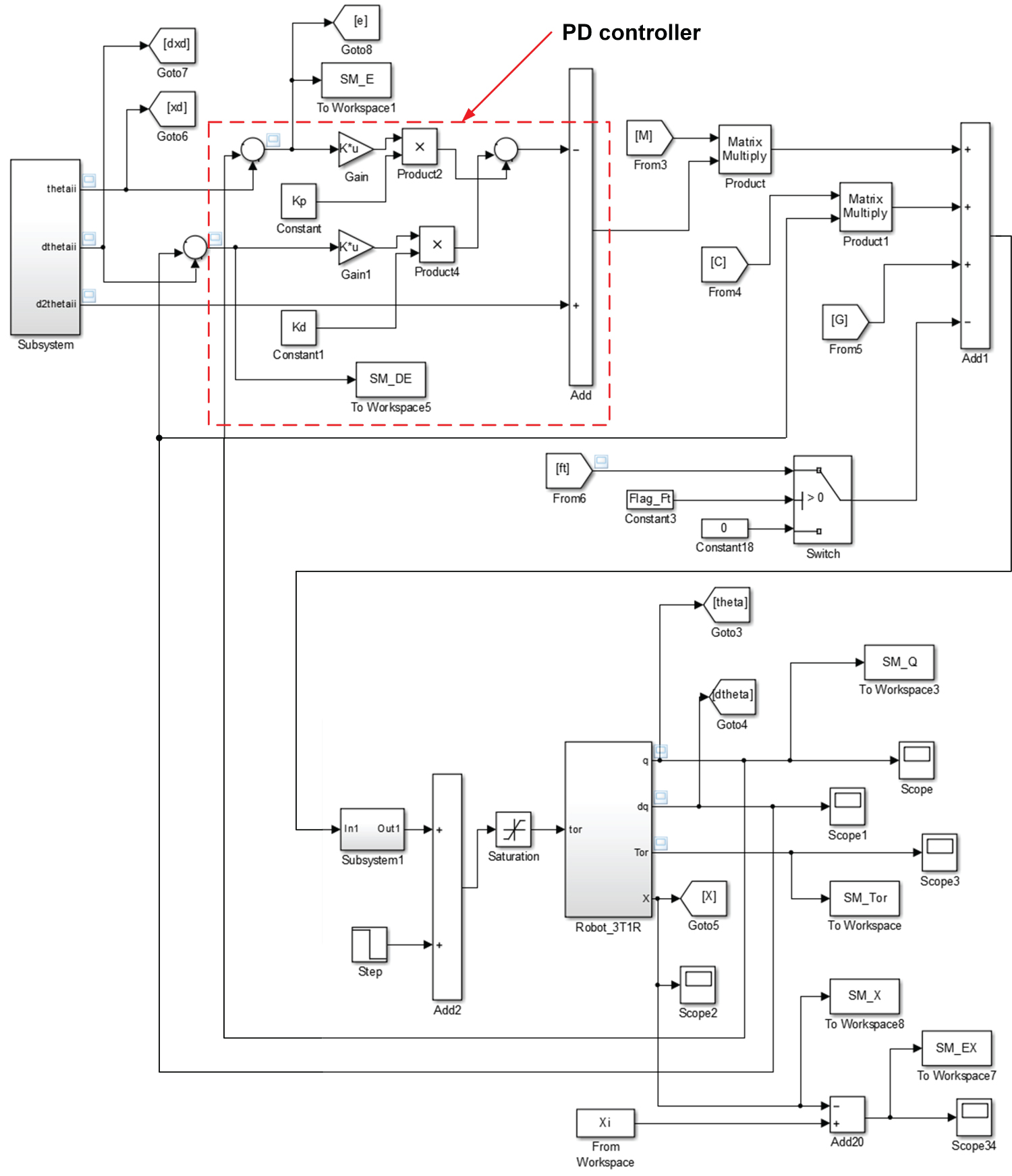
where KP = kP I4 and KD = kDI4 are the proportional and derivative gains matrices, respectively, and θ and θd are the actual and desired vector of joint variables. The corresponding controller is depicted in Figure 4. To ensure the control precision, the following optimization problem is formulated to minimize the errors of the joint variables:
where |e(t)| represents the 2 norm of the vector of the tracked joint errors.
Simulation and Experimental Tests
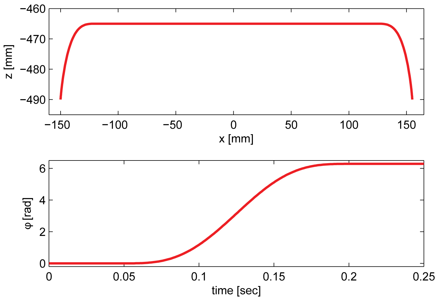
In this work, the dynamic simulation and experimental measurement are carried out along a testing trajectory defined in [14] lying in the x-z plane, as displayed in Figure 5. As most of the components are made of lightweight material, the structural stiffness of the robot under study is not as high as Quattro, thus, the working cycle is set to 120 cycles per minute (cpm)d. The links and sub-platforms are weighed as listed in Table 1, together with the geometric parameters.
dHere, a cycle is defined as the movement along a trajectory of 25 mm × 305 mm × 25 mm with a 1 kg payload per minute, which can be replaced by 25 mm × 300 mm × 25 mm in the definition of Adept test cycle [46].Simulation tests
A testbed, as depicted in Figure 6, was built in the Simscape module of Matlab/simulink to analyze the dynamic behavior of the robot and to validate the controller parameters.
Solving the optimization problem (26) in connection with the implementation of the dynamic simulation, the optimized control variables are found as
kP = 955; kD = 1000; λ = 0.5 (27)
It should be noted that the solved control variables may not be the global optimum, while, they can provide acceptable accuracy of trajectory tracking without high computational cost.
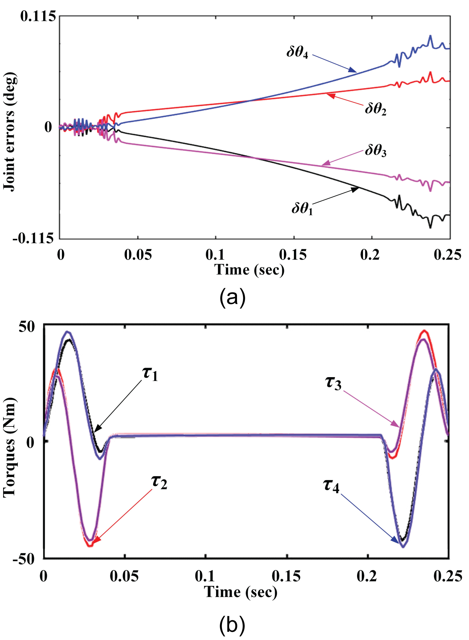
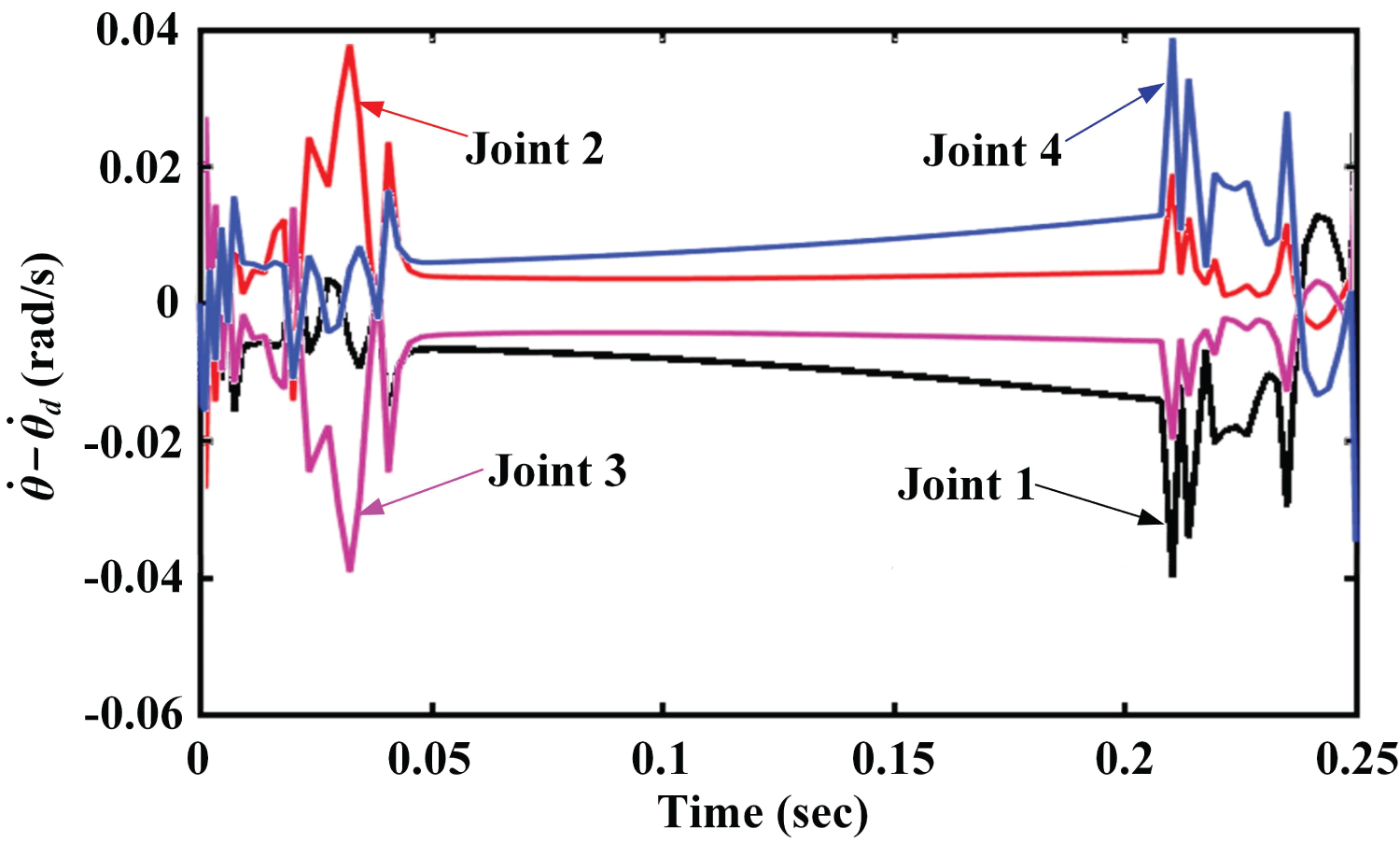
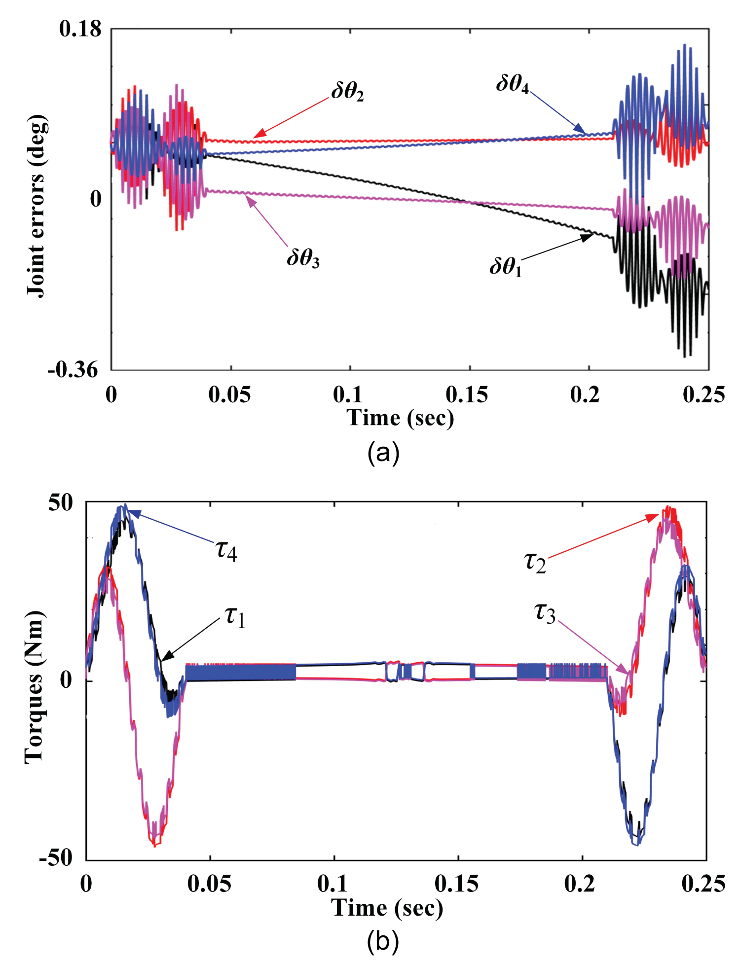
With the control variables in Eq. (27), dynamic simulation results along the trajectory defined in Figure 5 are shown in Figure 7, Figure 8 and Figure 9. Figure 7a depicts the tracked errors of the actuated joint variables, from which it is seen that the magnitudes of the joint errors increase from the starting point to the end, without the convergence. The corresponding time-varying joint torques are displayed in Figure 7b, in which the maximum torques occur in the period of acceleration/deceleration, equalling to 48 Nm approximately for joints 2 and 4. Similar to the joint errors θ-θd, the errors of the joint rates have sharp fluctuations when the robot end-effector accelerates or decelerates, compared to the smooth movement when the MP moves with constant velocities.
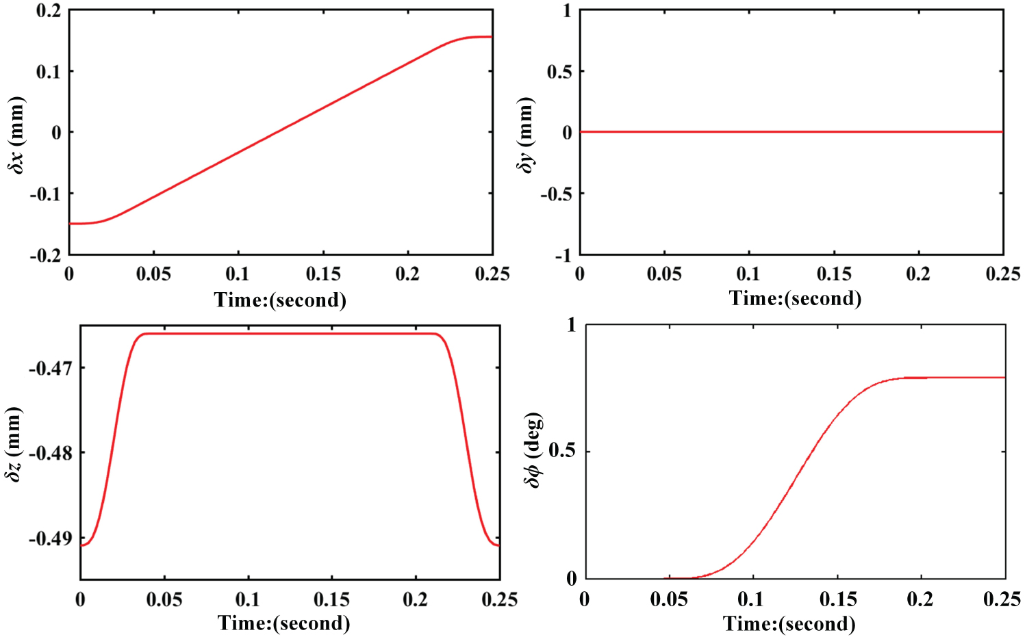
The tracked MP pose errors are displayed in Figure 9, wherein the maximum positioning errors appears at the z-coordinate with δz = -0.491 mm, and the maximum orientation error is equal to 0.8°. This means that the design control scheme can meet the precision requirements in most PnP operations for industrial applications.
Experimental evaluation
Tracking the prescribed PnP testing trajectory, the actual joint errors and torques are read from the motor encoders, as depicted in Figure 10. Compared to the simulation results, the experimental measurements have significant buffetings, particularly, in the period of acceleration/deceleration. The possible reasons may include the irregular friction and backlash of the kinematic pairs.
Referring to the MP pose errors in Figure 9, the predicted actual position and orientation errors generated by the joint errors in Figure 10a may reach to 1 mm and 1.5°, which are still acceptable for most industrial sectors in terms of PnP operations that do not require quite high accuracies. Comparing Figure 10b to Figure 7b, the changes of the measured joint torques have similar varying trends with simulated ones, which reaches to a good agreement, despite the presence of fluctuations that are ignorable when reduction gearbox is installed between the motors and active links. The comparison between the simulation tests and experimental measurements implies that the developed dynamic model and controller can work effectively for the robot under study, with a reasonable tradeoff between control accuracy and implementation complexity.
Conclusion
This paper presents the robot dynamics of a four-limb parallel Schoenflies-motion generator, which is characterized along with a physical prototype of this kinematic chain. The concise robot dynamics is modeled with principle of virtual work for the deployment in control design. The computed torque controller is designed by optimizing the control variables to minimize the tracked joint errors.
Simulation tests and experimental measurements are carried out along a trajectory of a picking testing cycle, both of which shows that the pose errors of the mobile platform are acceptable for industrial application. Experiments are implemented by observing the joint dynamics to evaluate the developed controller in comparison with the simulation results. The comparison shows a good agreement between the simulation and experimental results and the measurements validates the effectiveness of the developed dynamic control strategy. Future work will focus on the integrated advanced control design for improvement of control precision and buffeting suppression.
Acknowledgement
The supports from Fundamental Research Funds for the Central Universities (No. DUT19JC25), Natural Science Foundation of Liaoning Province (No. 20180520028), and China Scholarship Council (CSC No. 201906065026) are gratefully acknowledged.
References
- R Clavel (1990) Device for the movement and positioning of an element in space. US Patent No. 4,976,582.
- F Pierrot, O Company (1999) H4: A new family of 4-dof parallel robots. 1999 IEEE/ASME International Conference on Advanced Intelligent Mechatronics (Cat. No.99TH8399), Atlanta, GA, USA, 508-513.
- O Company, S Krut, F Pierrot (2006) Internal singularity analysis of a class of lower mobility parallel manipulators with articulated traveling plate. IEEE Transactions on Robotics 22: 1-11.
- S Krut, M Benoit, H Ota, et al. (2003) I4: A new parallel mechanism for Scara motions. 2003 IEEE International Conference on Robotics and Automation (Cat. No.03CH37422) 2: 1875-1880.
- V Nabat, M Rodriguez, O Company, et al. (2005) Par4: Very high speed parallel robot for pick-and-place. 2005 IEEE/RSJ International Conference on Intelligent Robots and Systems, Canada, 553-558.
- F Pierrot, V Nabat, O Company, et al. (2009) Optimal design of a 4-DOF parallel manipulator: From academia to industry. IEEE Transactions on Robotics 25: 213-224.
- S Krut, O Company, V Nabat, et al. (2006) Heli4: A parallel robot for scara motions with a very compact traveling plate and a symmetrical design. 2006 IEEE/RSJ International Conference on Intelligent Robots and Systems, Beijing, China, 1656-1661.
- X Kong, CM Gosselin (2004) Type synthesis of 3T1R 4-DOF parallel manipulators based on screw theory. IEEE Transactions on Robotics and Automation 20: 181-190.
- G Gogu (2007) Structural synthesis of fully-isotropic parallel robots with Schonflies motions via theory of linear transformations and evolutionary morphology. European Journal of Mechanics-A/Solids 26: 242-269.
- PL Richard, CM Gosselin, X Kong (2007) Kinematic analysis and prototyping of a partially decoupled 4-DOF 3T1R parallel manipulator. ASME J Mech Des 129: 611-616.
- S Liu, T Huang, J Mei, et al. (2012) Optimal design of a 4-DOF SCARA type parallel robot using dynamic performance indices and angular constraints. ASME J Mech Robot 4: 031005.
- F Xie, X Liu (2015) Design and development of a high-speed and high-rotation robot with four identical arms and a single platform. ASME J Mech Robot 7: 041015.
- TL Yang, A Liu, H Shen, et al. (2018) Topology design of robot mechanisms. In: Topology design of (3T-1R) parallel mechanisms, Springer Singapore, 207-236.
- G Wu, Z Lin, W Zhao, et al. (2020) A four-limb parallel schonflies motion generator with full-circle end-effector rotation. Mechanism and Machine Theory 146: 103711.
- G Wu, S Bai, P Hjornet (2016) Architecture optimization of a parallel schonflies-motion robot for pick-and-place applications in a predefined workspace. Mechanism and Machine Theory 106: 148-165.
- G Wu, S Bai, S Caro (2018) A transmission quality index for a class of four-limb parallel Schonflies motion generators. ASME J Mech Robot 10: 051014.
- Q Li, FX Wu (2004) Control performance improvement of a parallel robot via the design for control approach. Mechatronics 14: 947-964.
- F Bourbonnais, P Bigras, IA Bonev (2015) Minimum-time trajectory planning and control of a pick-and-place five-bar parallel robot. IEEE/ASME Trans Mechatron 20: 740-749.
- X Zhang, R Sorensen, MR Iversen, et al. (2018) Computationally efficient dynamic modeling of robot manipulators with multiple flexible-links using acceleration-based discrete time transfer matrix method. Robotics and Computer-Integrated Manufacturing 49: 181-193.
- PK Eskandary, J Angeles (2018) The dynamics of a parallel Schonflies-motion generator. Mechanism and Machine Theory 119: 119-129.
- X Zhang, J Liu, J Feng, et al. (2020) Effective capture of nongraspable objects for space robots using geometric cage pairs. IEEE/ASME Trans Mechatron 25: 95-107.
- Z Ji (1993) Study of the effect of leg inertia in Stewart platforms. [1993] Proceedings IEEE International Conference on Robotics and Automation, 121-126.
- A Codourey (1998) Dynamic modeling of parallel robots for computed-torque control implementation. Int J Robot Res 17: 1325-1336.
- FL Lewis, DM Dawson, CT Abdallah (1993) Control of robot manipulators. Prentice Hall PTR.
- H Cheng, YK Yiu, Z Li (2003) Dynamics and control of redundantly actuated parallel manipulators. IEEE/ASME Transactions on Mechatronics 8: 483-491.
- A Vivas, P Poignet (2005) Predictive functional control of a parallel robot. Control Engineering Practice 13: 863-874.
- R Dahmouche, N Andreff, Y Mezouar, et al. (2010) Effecient high-speed vision-based computed torque control of the orthoglide parallel robot. 2010 IEEE International Conference on Robotics and Automation, 644-649.
- A Zubizarreta, M Marcos, I Cabanes, et al. (2011) A procedure to evaluate extended computed torque control configurations in the Stewart-Gough platform. Robotics and Autonomous Systems 59: 770-781.
- K Liu, J Xu, Z Ge, et al. (2017) Robust control of 3-DOF parallel robot driven by PMAs based on nominal stiffness model. Journal Advanced Robotics 31: 531-543.
- JJ Craig, P Hsu, SS Sastry (1987) Adaptive control of mechanical manipulators. Proceedings 1986 IEEE International Conference on Robotics and Automation 6: 16-28.
- JJE Slotine, W Li (1991) Applied nonlinear control. Pearson.
- WW Shang, S Cong, Y Ge (2012) Adaptive computed torque control for a parallel manipulator with redundant actuation. Robotica 30: 457-466.
- Y Chen, G Ma, S Lin, et al. (2012) Adaptive fuzzy computed-torque control for robot manipulator with uncertain dynamics. Int J Adv Robot Syst 9: 237.
- S Hyon, D Suewaka, Y Torii, et al. (2017) Design and experimental evaluation of a fast torque-controlled hydraulic humanoid robot. IEEE/ASME Transactions on Mechatronics 22: 623-634.
- A Koessler, N Bouton, S Briot, et al. (2019) Linear adaptive computed torque control for singularity crossing of parallel robots. ROMANSY 22-Robot Design, Dynamics and Control, Springer, 222-229.
- W Shang, S Cong (2009) Nonlinear computed torque control for a high-speed planar parallel manipulator. Mechatronics 19: 987-992.
- Q Li, SK Tso, WJ Zhang (1998) Trajectory tracking control of robot manipulators using a neural-network-based torque compensator. Proceedings of the Institution of Mechanical Engineers, Part I: Journal of Systems and Control Engineering 212: 361-372.
- Z Yang, J Wu, J Mei (2007) Motor-mechanism dynamic model based neural network optimized computed torque control of a high speed parallel manipulator. Mechatronics 17: 381-390.
- G Wu, H Shen (2021) Parallel PnP robots. Research on Intelligent Manufacturing. Springer, Singapore, 7.
- JG Jalon, E Bayo (2012) Kinematic and dynamic simulation of multibody systems: The real-time challenge. Springer Science & Business Media.
- S Bai, L Zhou, G Wu (2015) Handbook of manufacturing engineering and technology. Manipulator Dynamics, Springer, 1855-1872.
- PE Nikravesh (1988) Computer-aided analysis of mechanical systems. Prentice-Hall, Inc.
- S Briot, W Khalil (2015) Dynamics of parallel robots. Mechanisms and Machine Science. Springer International Publishing, AG, Switzerland.
- Z Lin, G Wu, X Zhang, et al. (2020) Dynamics modeling and torque feedforward based PD control of a high-speed parallel manipulator. The 4th International Workshop on Fundamental Issues, Applications and Future Research Directions for Parallel Mech-anisms/Manipulators/Machines, Belfast, UK.
- Z Song, J Yi, D Zhao, et al. (2005) A computed torque controller for uncertain robotic manipulator systems: Fuzzy approach. Fuzzy Sets Systems 154: 208-226.
- JF Gauthier, J Angeles, S Nokleby (2008) Optimization of a test trajectory for SCARA systems. Advances in Robot Kinematics: Analysis and Design, Springer Netherlands, Dordrecht, 225-234.
Corresponding Author
Guanglei Wu, School of Mechanical Engineering, Dalian University of Technology, Dalian, China.
Copyright
© 2020 Wu G, et al. This is an open-access article distributed under the terms of the Creative Commons Attribution License, which permits unrestricted use, distribution, and reproduction in any medium, provided the original author and source are credited.