Bio-Inspired Soft Robot for Locomotion and Navigation in Restricted Spaces
Abstract
Soft robotics have been shown to be particularly versatile for accessing restricted and hazardous environments, such as nuclear and chemical processing plants, and pipelines. This paper presents a bio-inspired soft robot capable of propelling itself inside a cylindrical space. The continuum soft robot consists of three main sections, which, with coordinated inflation and deflation, enable a controlled locomotion of the robot. The sections are composed of two types of soft actuator: Radially-expandable cylindrical modules (RECMs) and vacuum-actuated muscle-inspired pneumatic structures (VAMPs). In this paper, the details of the soft actuators' design and support structures are described. Tests conducted on the actuators verify their suitability for performing a number of specific motion tasks, including bending and navigation in restricted vertical and horizontal environments. The preliminary experimental results indicate that the bio-inspired design approach enables the soft components to move dexterously inside the restricted environment, perform longitudinal shifts of 28% its original length in one motion cycle, and lift loads up to 150 g per VAMP. These observations were confirmed using finite element analysis. The robot can also be safely and remotely operated to enable an efficient control of the robots' soft actuators. The possibility of moving with infinite degrees of freedom and safely interact with humans provide the robot with the potential of being employed in wide ranging application in industry and research.
Introduction
Navigation in spaces inaccessible for direct human inspection requires robots that can operate in restricted, and possibly hazardous environments. However, traditional robots, which are usually composed of electronically operated rigid components, are frequently inadequate for this task as their rigid structure does not allow them to adapt to a constrained path, and are often easily damaged due to a variety of environmental conditions (e.g. moisture, corrosion, and radiation). In recent years, there has been a growing interest in the study of unconventional materials to build more compliant robots [1-3], often known as soft robots, by taking inspiration from animals in order to develop more resilient and flexible designs that require few or no internal electronic components, and that can withstand challenging environments [4-6]. These properties can be extremely useful in scenarios such as pipelines inspections: The restricted space makes it impossible for direct human inspection, and a hazardous and harmful environment requires high endurance and adaptability. The robots normally deployed for pipeline inspections utilize locomotion techniques such as snake-like motion [7], wheels [8], screws [9], or a combination of techniques [10]. However, the hard robots cited present critical issues. For example, screw-actuated and wheeled robots can provide efficient and fast locomotion, but they usually only fit in pipelines with large diameters. Additionally, the rigid structure and weight make these robots unsuitable for inspections of unstructured pipelines or where the environment is altered by external factors.
Soft robots, comprised predominantly of compliant materials, have also been considered for pipe-crawling [11-13]. The locomotion of these robots is enabled by either soft inflatable components or vacuum powered actuators which often perform a worm or traveling wave type motion to propel the robot forward. The locomotion method used is essentially based on two design characteristics: A set of anchors that press on the pipe wall, and a linear actuator segment which allows the longitudinal movement of the robot via extension. By adopting light and compliant materials, the robots can effectively inspect pipelines of many different internal diameters without being affected by the conditions of the pipeline. One of the limitations of the devices proposed in [11] and [12] is their inability to actively steer when the pipeline presents bends and joints. To overcome this obstacle, continuum robots that can bend with a constant curvature have been developed [14,15]. Continuum actuators can grasp delicate objects [16,17], provide legged locomotion [18,19] and other complex motions [20-22]. The design proposed by [23] shows that by using a structure consisting of three parallel actuators, it is possible to bend the robot by applying different pressures on each actuator. A characteristic of the continuum robot in [23] is that the anchors were replaced by two flexible feet that enhance the friction with the pipe wall and enable the robot to crawl. While weight efficient, this design choice ultimately makes it unfit for oily or unstructured environments. It is apparent that an active component is needed to actuate both the robot anchor and steering in the pipeline.
Despite being made of soft materials, previous research in crawling robots such as [11] and [12] lack a biomimetic approach that can recreate biological structures which have been shown to have useful functionality, such as high dexterity. Previous works on recreating these structures include an octopi-like robot [24,25], muscle-like linear actuators [26], muscular hydrostats [27], elephant trunk-like actuators [28] and earthworm/inchworm-like robots [29,30]. The use of a parallel structure to allow the steering in soft robots has been employed in previous works for crawling and manipulation [23,31]. However, the use of vacuum-powered actuators with an internal structure that closely mimics biological muscles and enable both the locomotion and active steering within a pipeline has not yet been explored. For example, earthworm soft robots, such as the one proposed in [29], despite using a biomimetic approach for the muscle design, does not possess an active steering mechanism.
In this work, a soft continuum robot that can navigate and actively bend through constrained and hazardous spaces, such as a pipeline, is described. This robot achieves both extension and bending by combining inflatable anchors Radially Expandable Cylindrical Modules (RECMs) with a continuum middle section, which incorporates parallel biomimetic Vacuum-Actuated Muscle-Inspired Pneumatics actuators (VAMPs) that enable bidirectional locomotion. The VAMPs utilize both stiff and soft components to improve its efficiency and force output. The RECMs can adapt to the pipeline, which can present unstructured characteristics (change in diameter, corners, etc.) or realistic environmental conditions (e.g. oily surfaces, etc.). The robot also includes an internal space to allow the insertion of devices, such as cameras or other sensor units. This will enable the soft robot to perform inspections and be easily controlled by a human operator.
The paper is organized as follows. Section 3 describes the locomotion techniques used, and the design of the soft actuators. Section 4 shows the tests performed on the individual actuators, the horizontal locomotion, the vertical locomotion, and the bending ability of the soft robot. Section 5 summarizes the conclusions and results. Details of the fabrication process are provided in the Supplementary Material.
Design
Locomotion technique
The full design of the robot consists of five soft actuators which are contracted and expanded in a coordinated fashion. These consist of three long parallel VAMPs, which make up the continuum midsection, and two RECMs at the ends. The expansion and contraction are achieved through the pressurization of air, which has the advantage of relative rapid actuation, ease of use, and being environmentally friendly [26].
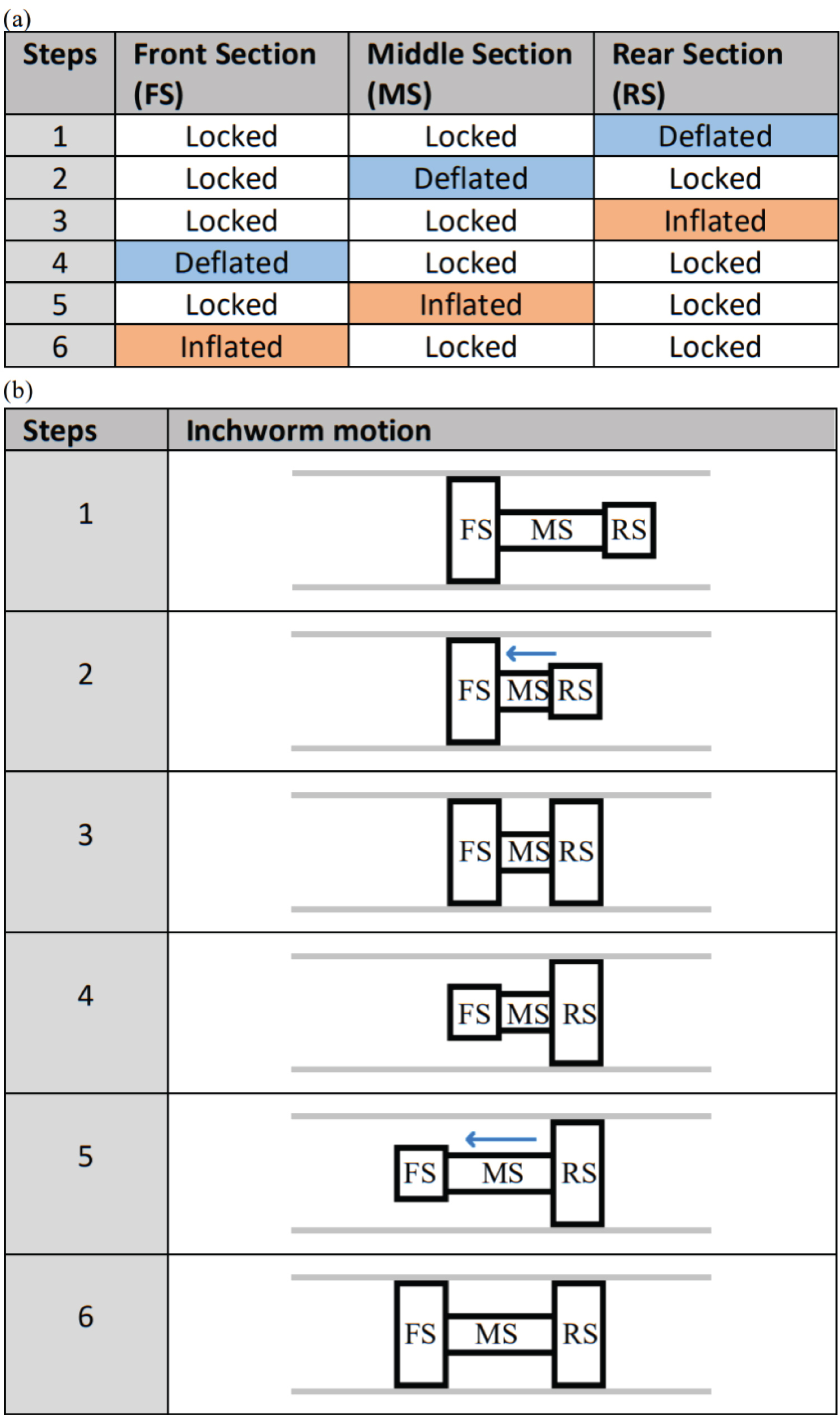
Inchworm actuation is used to enable the bidirectional locomotion of the robot [11] by actuating the sections of the robot in a synchronized manner. This motion can be modelled as a series of steps where each section can be in three different conditions: Inflated, locked and deflated [11] (see Figure 1). During inflation and deflation, the actuator in each section increases and decreases in volume respectively, while when locked, it maintains the previous state. The motion cycle is summarized by six steps (Figure 1).
To enable active steering, different pressures are applied to the three parallel VAMPs: The robot bends in the direction of the actuator with the lowest pressure.
Vacuum-actuated muscle-inspired pneumatic design
The middle section of the robot consists of three VAMPs and actuation is enabled by applying a vacuum resulting in a reduction in length. By choosing to apply a vacuum over inflation, the possible risk of rupture of the elastomer caused by over-inflation is minimized.
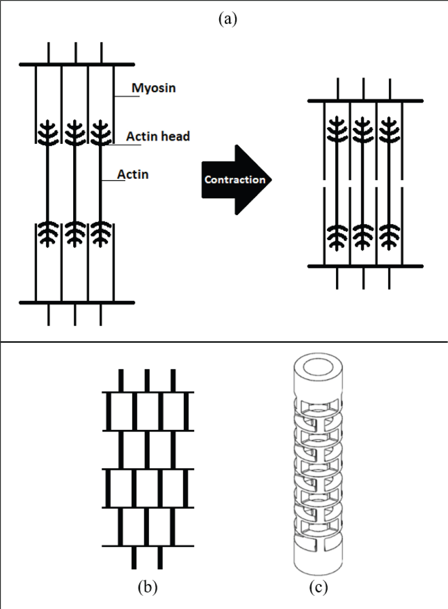
The structural pattern is inspired by actual organic muscle systems and a previous work in bio-inspired buckling muscles [26]. A biological muscle comprises two fundamental components, actin and myosin, which together form the sarcomere. This structure (see Figure 2a) enables contraction of the muscle according to a sliding filament model: The sarcomere shortens when the filaments of actin and myosin slide next to each other by using small actin heads that pull the filaments of myosin, resulting in the muscle contraction.
By simplifying this structure, the essential elements of the actuator consist of thick vertical beams, and thin horizontal beams which function as actin heads. These thin horizontal beams bend during contraction, allowing the vertical beams to slide next to each other, shortening the VAMP. The "brick wall" pattern obtained is shown in Figure 2b.
To transfer this geometry into the VAMP and minimize its volume, the brick wall pattern is constructed to fit in a cylindrical body (internal diameter: 15.40 mm - external diameter 25 mm). As shown in Figure 2c, the ends of the VAMP are thick, one of which allows the inlet/outlet of air. Each level in the pattern is composed of three vertical beams (height: 8 mm, width: 4.13 mm) which are uniformly and radially distributed along the circular section of the level and are connected to each other by horizontal beams (thickness: 1.5 mm). There is a fillet of 0.5 mm between the vertical and horizontal beams to improve robustness. Finally, when manufactured, the actuator will have an external layer 0.5 mm thick wrapped around the entire structure to seal the actuator and permit the creation of an internal vacuum.
Radial expandable cylindrical modules design
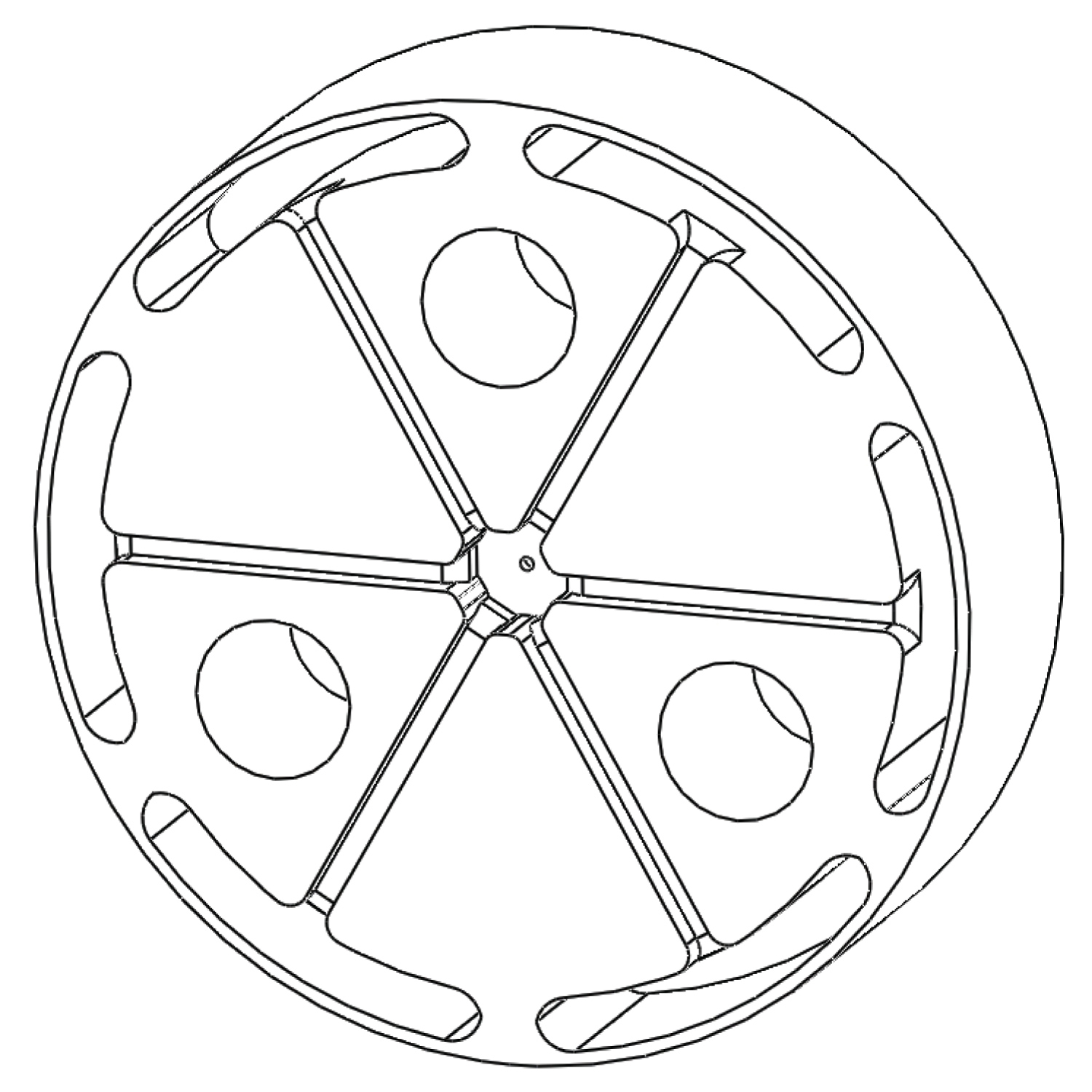
While the VAMPs provide a linear displacement, the RECMs allow the robot to anchor to the pipe by applying uniform pressure on the internal walls. The design is shown in Figure 3.
The component is a short cylindrical actuator (70 mm in diameter) composed of six chambers (15 mm deep) distributed near the curved surface and connected in the middle through six channels (2 mm × 2 mm cross-section). During the inflation, the six chambers expand and apply a uniform pressure on the inner wall of the pipe. The channel pattern is located on only one side of the actuator, while the other side consists of a 4 mm thick circular surface of elastomeric material (Ecoflex - see Supplementary Material). The actuator also exhibits three 11.50 mm wide holes located between the channels, which are used to connect the component to the VAMPs. The RECM has an additional circular layer that will seal the chambers and the air channels. To seal the channels, a nylon fabric impregnated with Ecoflex (0.5 mm thickness) was used. This creates a light and thin layer that prevents the deformation of the sides of the chambers during inflation.
Connections design
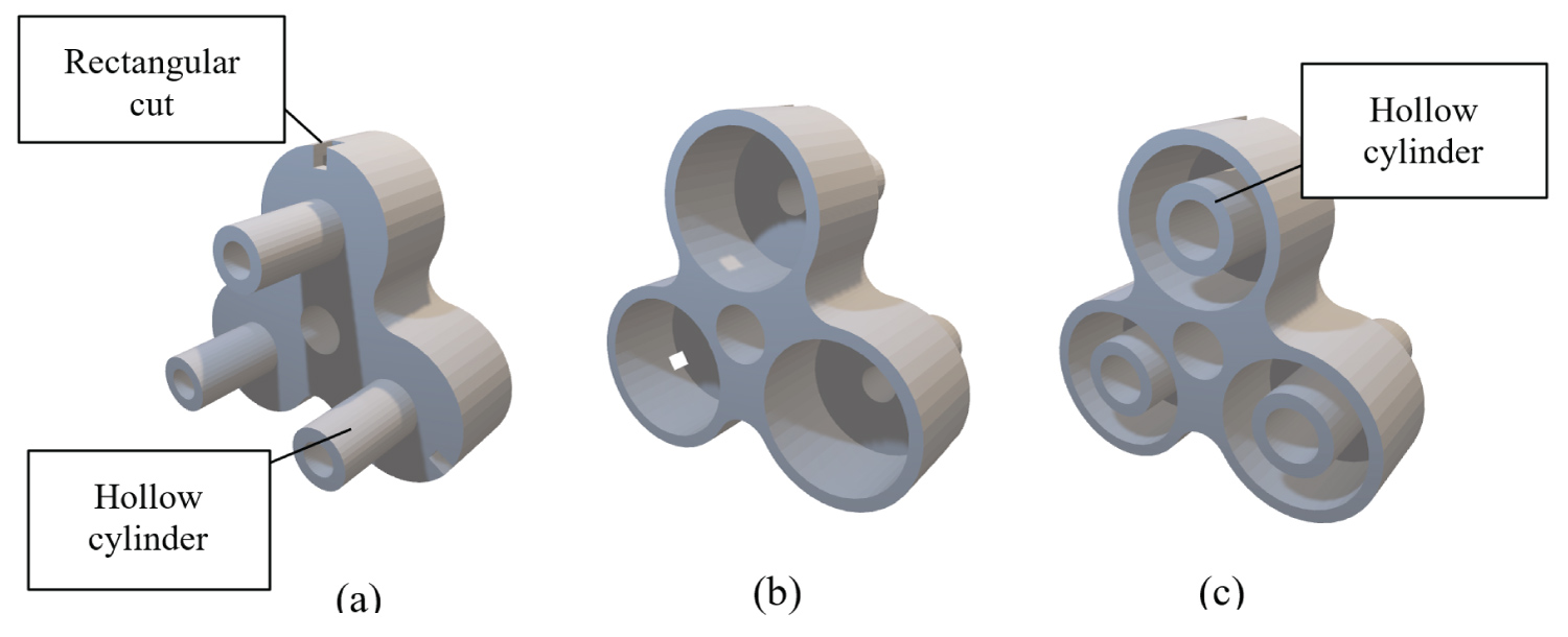
To assemble all the components, two connections were created using 3D printing, in this case, fused filament fabrication. The two 3D printed parts (Figure 4) have similar features: Three cavities (25.50 mm in diameter) to hold the ends of three VAMPs, and three hollow cylinders 20 mm long that will be inserted in the RECM. Each connection also has a hole of 10 mm diameter at the centre to facilitate the addition of an air supply system to the RECM, and three rectangular cuts at the base of the 25.5 mm cavities to ease the insertion of the VAMPs. The only design differences between the two connections are the additional hollow cylinders inside the cavities (Figure 4c) to fit the hollow end of the VAMP. The hollows in these cylinders are directly connected with those of the hollow cylinders on the opposite side (which are intended for the connection with the RECM) creating a continuous channel that allows to easily fit the air supply from the back of the soft robot.
Testing and Results
VAMP tests and results
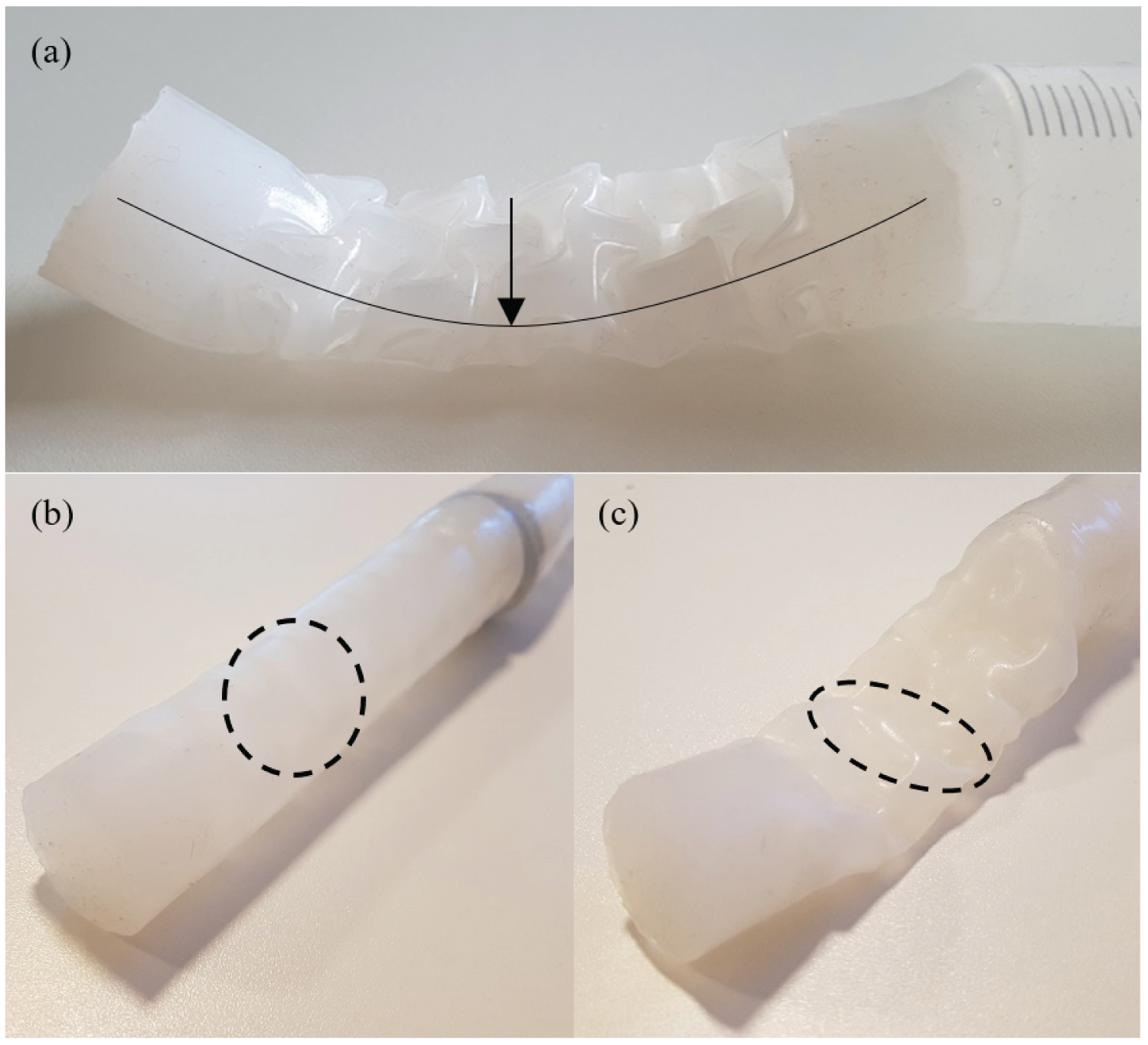
When vacuum was applied, the VAMP had a tendency to "flatten" transversely rather than contracting longitudinally (Figure 5a). By observing this undesired behavior, it was possible to notice that the horizontal beams were deformed by gravity, changing from a circular shape to an elliptical one (Figure 5b and Figure 5c), thus failing to pull the thick vertical beams into the empty space of the adjacent levels.
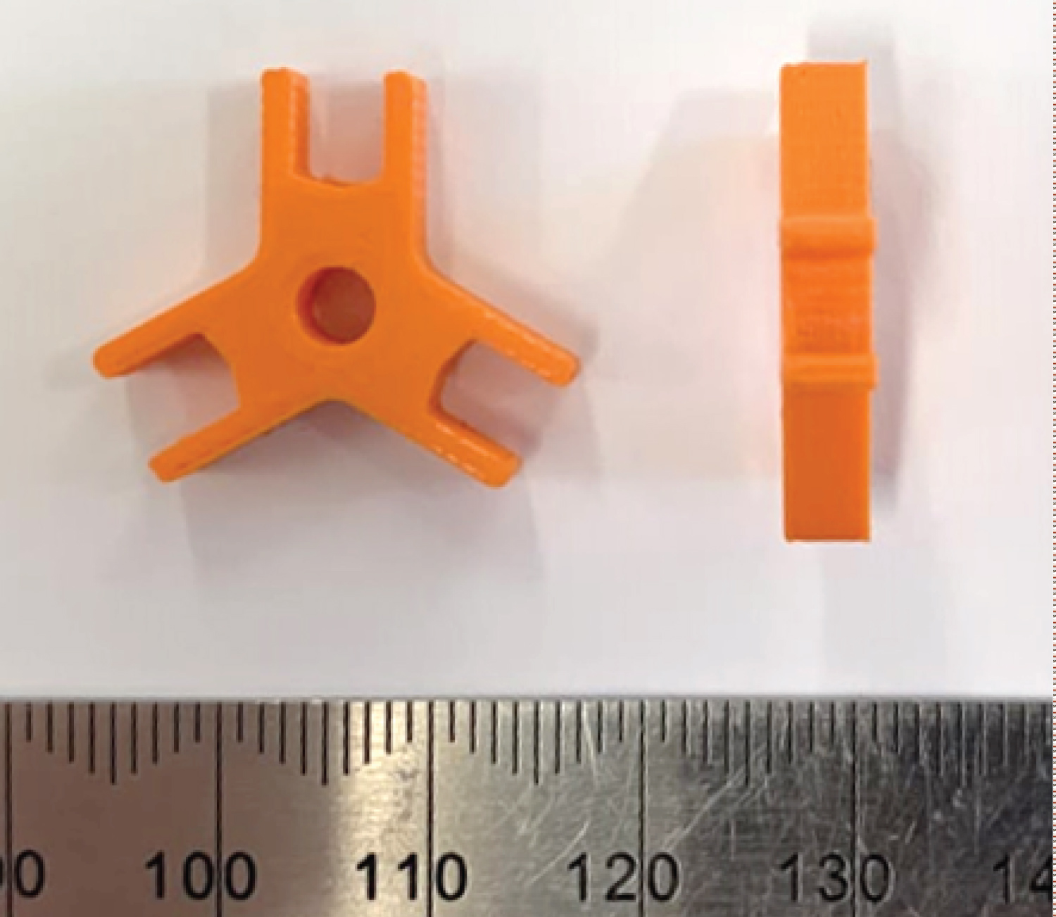
To prevent this behavior, small internal supportive components (Figure 6) were designed and manually inserted inside the VAMP. As seen, these structures consist of three radially positioned pairs of pegs designed to grip and maintain the position of the vertical walls of the internal brick structure of the VAMP elements shown in Figure 2. The design of these supportive components is such as not to impede the deformation of the cavities during deflation, whilst still preventing the collapse of the structure. When one of these components is added to each of the ten levels of the pattern within the VAMP, the deflation is facilitated by a 3.75 mm hole located at the center permitting airflow at every level of the actuator.
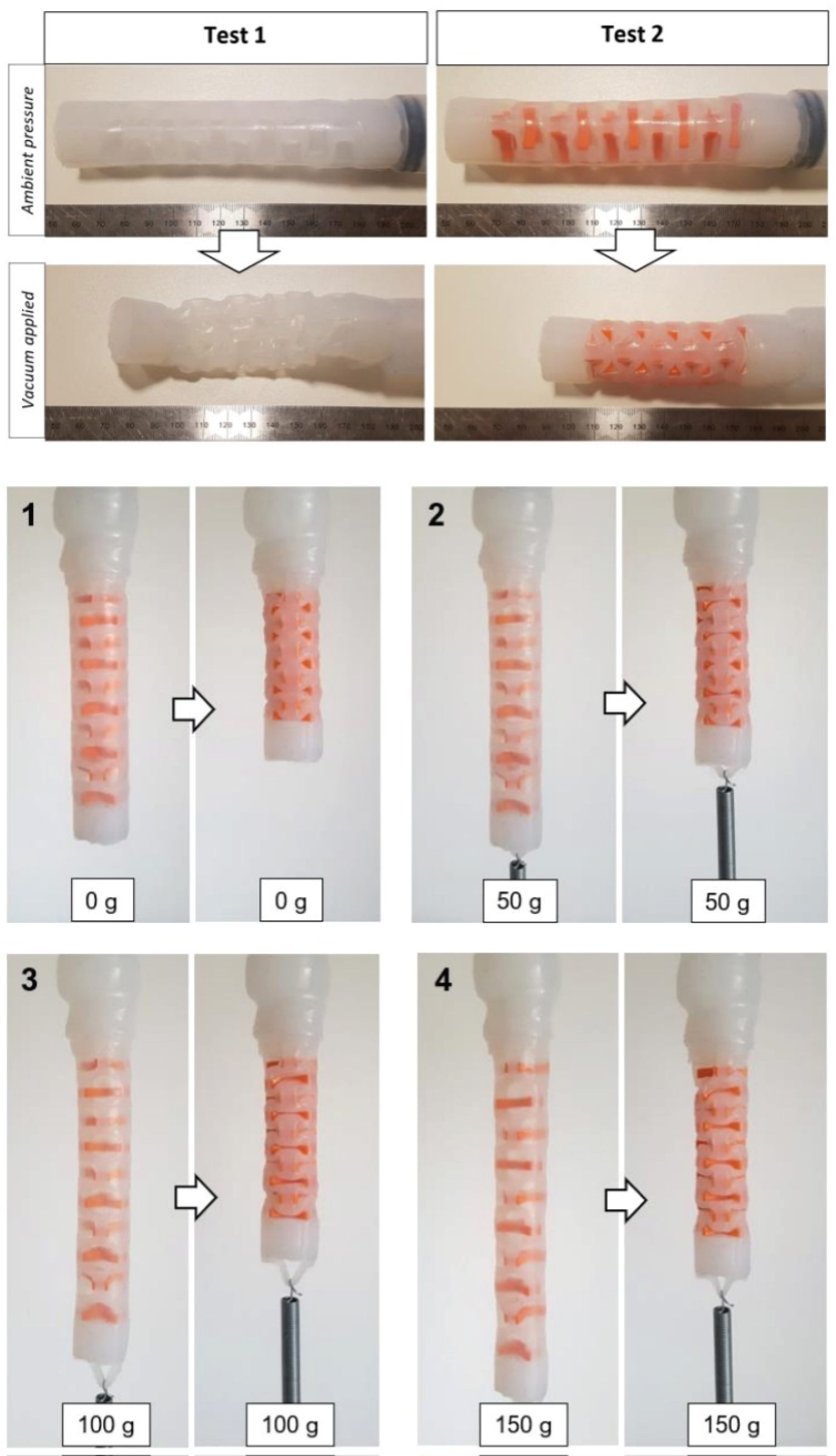
To verify the efficacy of the solution, two tests were performed in parallel (Figure 7). Both tests were executed by positioning the 129 mm long VAMP on a horizontal surface and observing the contraction of the actuator when vacuum was applied.
The first test was performed on an actuator without added components. A complete deflation was achieved after removing 40 cc of air and, when vacuum was applied, the actuator deflated without significant longitudinal deformation and collapsed under its own weight. After its contraction, the final length of the actuator varied between 110 and 115 mm, depending on the position in which the body of the actuator collapsed.
The second deflation test was performed using the same actuator but with 10 "beam holders". Due to the smaller internal volume of the cavity inside the actuator, the complete contraction was achieved after removing 33 cc of air. The contraction obtained from this configuration was significant and a consistent deformation pattern was observed throughout the VAMP [26]: The horizontal beams bended enabling the rigid vertical beams to slide into the empty spaces of the adjacent levels. The actuator contracted from 129 mm to 93 mm, corresponding to a shortening of 28%, and the body was able to maintain a cylindrical shape. Since the contraction is enabled solely by the patterned area of the structure, the 15 mm ends of the actuator could be ignored from the calculation of the length reduction. Therefore, the active part of the actuator contracted from 99 mm to 63 mm, showing it to be capable of contracting to about 36% of the original length. By comparison, the vacuum activated soft twisting actuators developed by Jiao, et al. [12] have a maximum height change less than 20 mm, the inflatable toroidal actuator-based pipe crawling robot developed by Adams, et al. [11] extends by 44 mm per cycle, and the extensible parallel-pipe-crawling robot developed by Zhang, et al. [13] can extend 55 mm when 100 kPa is applied. This is expected as actuators based on inflation do not have the same restrictions as those based on deflation, such as the proposed here, and therefore can exhibit a greater change in length given comparable initial dimensions. The stroke length exhibited by the VAMPs is easily increased by increasing the original length.
A vertical pulling test was then performed with the aim of observing the contraction when under load. The actuator was tested under four different loads (0, 50, 100, and 150 g) and the results of the tests are illustrated in Figure 7.
The self-weight of the VAMP is 38 g (internal components accounting for 7 g) and the performance of the VAMP in the vertical tests indicates that the actuators could withstand weights up to 150 g, corresponding to almost four times its own weight. The vertical contractions in Figure 7 show that, as the weight is increased, the structure of the VAMP can still shorten its length, but some thinner parts of the actuator, such as the external layer, start to stretch, reducing the magnitude of the contraction. Observing the VAMP at rest, it is possible to notice a deformation of the rectangular cells at each level, which start to assume an octagonal shape.
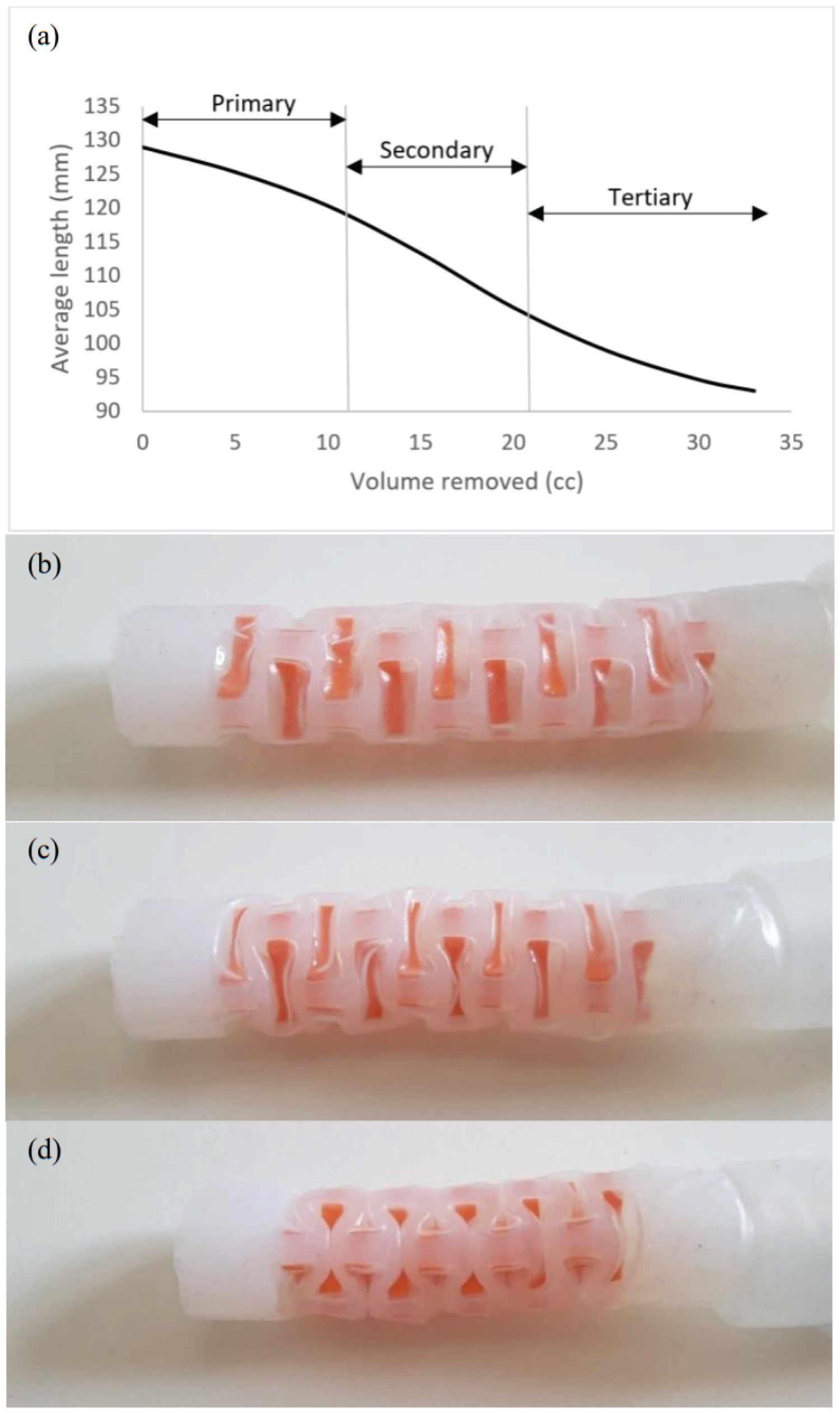
From the deflation curve in Figure 8a, three regimes can be distinguished: Primary, secondary, and tertiary contraction. This behavior can be explained considering the structure and contraction mechanism of the VAMP.
In the primary contraction, the external layer is the first part of the actuator to be pulled inside because of the internal vacuum (Figure 8b). Due to its lower thickness, the external layer is more affected by the internal pressure difference and principally enables the first phase of the contraction by bringing the vertical beams of the internal structure closer. In this phase, the internal structure is just partially engaged due to its higher thickness. As more air is removed, the internal structure starts to be actively involved in the shrinkage, which results in the formation of a serpentine pattern (Figure 8c) [22]. This is the secondary phase and is enabled by the combined elastic contraction of both external layer and internal structure of the VAMP. In this phase, the curve can be approximated to a linear function and the soft robotic muscle has a constant length reduction, allowing to easily predict the contraction per internal pressure applied. In the tertiary regime, the external layer is almost entirely pulled within the internal structure, making its contribution to the contraction almost negligible (Figure 8d). As can be seen in Figure 8a, the deformation is smooth throughout the different phases with no sudden transitions being observed. The lack of sudden changes between phases can be understood by considering the complex structure of the VAMP and the properties of the elastomer. As will be noted, the VAMP is made up of many surfaces that come into contact during deflation. Very minor fluctuations in the local geometry in the structure will mean that various surfaces will come into contact at very slightly different times, thus softening any impact. This coupled, with the compliance of the elastomer, means that the effects of contact within the VAMP structure during deformation are subtle.
The extension of the VAMPs under pressure and load was further investigated using finite element analysis (FEA). The simulations were conducted using ANSYS 2020 R2 on a PC with an Intel® Core™ i7-9750H CPU @ 2.60 GHz processor and 16 GB of RAM. The geometry consisted of a single VAMP in isolation halved along the axial plane in order to take advantage of symmetry. The VAMP was defined as Ecoflex (elastic modulus 66 kPa, Poisson's ratio 0.48 - see supporting information). The mesh (see Figure 9) consisted of 37,113 elements, which included 20,883 SOLID187 elements and 16,230 TARGE170/CONTA174 elements. Self-contact with the internal and the external faces of the VAMP respectively were defined as rough and symmetric with small sliding allowed. Automatic bisection was used to predict changes in contact. The contact algorithm was the augmented Lagrange method with contact detection at the Gauss integration points. The simulation was a static structural simulation. The equation solver was sparse, with the globally assembled matrix being symmetric. A direct solver was used.
The outer faces of the VAMP were kept at atmospheric pressure, with the end of the VAMP connected to the tubing fixed in position and rotation. An internal pressure was applied to the inner faces of the VAMP. This was ramped from 0-6 kPa below atmospheric pressure in 30 sub steps. In Figure 10a it can be seen that this deflation resulted in a maximum retraction, or reduction in VAMP length, of 36.441 mm. This is consistent with the experimental results. However, in Figure 10b, the axial retraction as a function of pressure seems to be more linear as compared to that observed experimentally (see Figure 8) even though the shape of the deflated VAMP determined in experiment and simulation is quite comparable. It is possible that this due to additional interactions with the internal support structures not captured in the FEA. The effects of adding weight to the end of the VAMP was also investigated. In these simulations the boundary conditions remained the same as those described previously, with the internal pressure kept constant at 6 kPa below atmospheric pressure and with a force applied to the free end to represent the weight added. The weight was increased from 0 to 1.5 N in 30 sub steps in a manner comparable to the experiments shown in Figure 7. As seen in Figure 10c, VAMP extended only 2.8 mm under the maximum load, again comparable with what was observed experimentally.
RECM tests and results
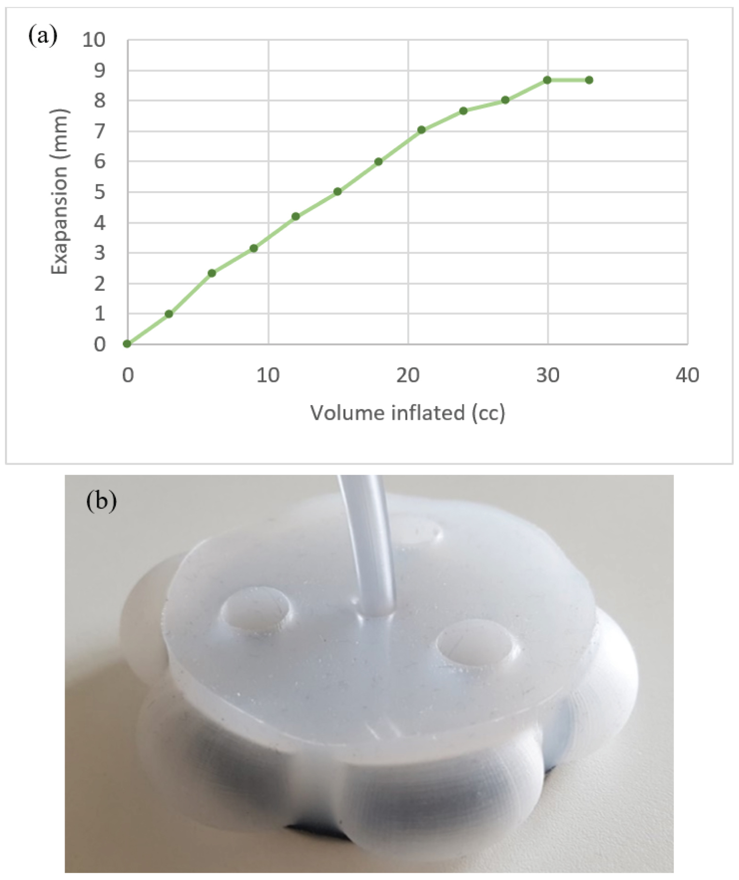
From Figure 11a, it can be observed that most of the expansion curve of the RECM can be approximated as a linear function. After 24 cc of air has been supplied, the expansion slows down and starts to reach a maximum expansion of about 9 mm. From the results it can be concluded that the RECM, whose original diameter is 70 mm, reaches a maximum diameter of about 88 mm during the expansion (see Figure 11b). Therefore, the force applied by the robot on the pipe wall with internal diameter of 88 mm is zero. This is because the actuator has reached its maximum expansion and is unable to provide additional pressure on the wall. By comparison, the radial actuator of the worm inspired robot developed by Caleron, et al. [29] expands from 35 mm to 62 mm under an applied pressure of 20.7 kPa, whilst conversely the nylon bellows-based actuator developed by Adams, et al. [11] actually reduces in radial diameter, because the of the relatively stiff material, but can exert a force of up to 33 N when a pressure of 55 kPa is applied (8 kPa is required to inflate the actuator before a force can be exerted). As can be seen in the FEA simulations below, actuation is achieved with this proposed actuator at much power pressures.
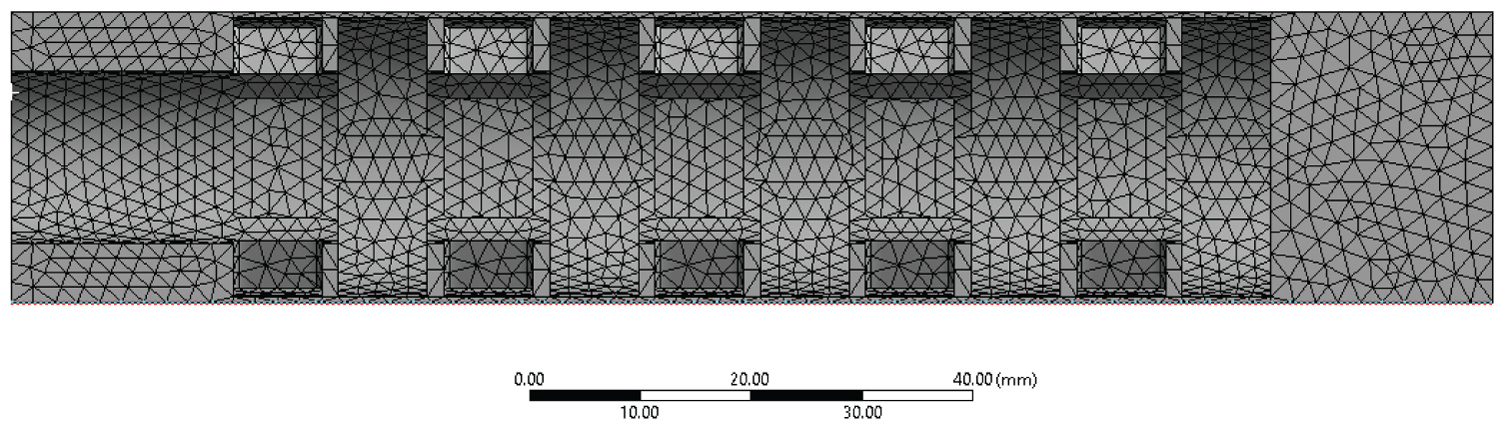
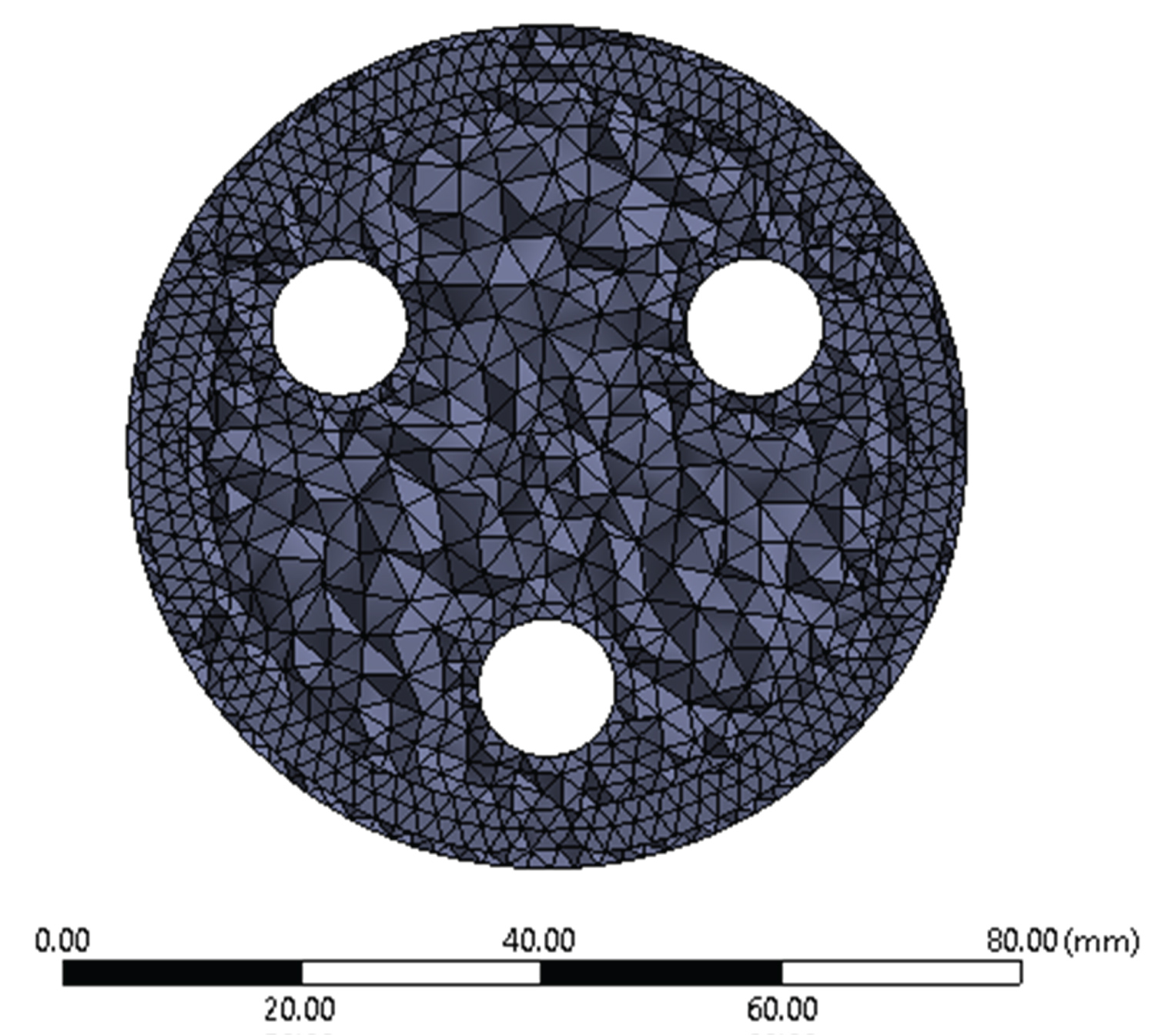
Radial expansion of the RECM within pipes of different diameters was simulated using FEA to ascertain the contact, or reaction, force between the RECM and the inside of the pipes as a function of pressure. The analysis was conducted using in ANSYS 2020 R2. The geometry simulated was that shown in Figure 3. The pipe, modelled as a hollow thin walled (thickness 2 mm) cylinder with length 50 mm (sufficient to allow full contact), was defined as rigid. The RECM was defined as Ecoflex (elastic modulus 66 kPa, Poisson's ratio 0.48). The mesh used in the RECM is shown in Figure 12. The total mesh consisted of 85,148 elements, consisting of 64,726 SOLID 187 elements and 20,422 contact (TARGE170 and CONTA174) elements. Contact between the RECM and the inner surface of the pipe was defined as rough. The contact algorithm was the augmented Lagrange method with detection at the Gauss integration points. A pinball radius of 5 mm was used with automatic bisection used to predict for impact and an abrupt contact change. The inner surface of the rigid pipe was set as fixed in displacement and rotation, as was the faces of the cylindrical holes in the RECM which are where the connectors (Figure 4) will be attached. A pressure was applied normal to the inner faces of the cavities within the RECM.
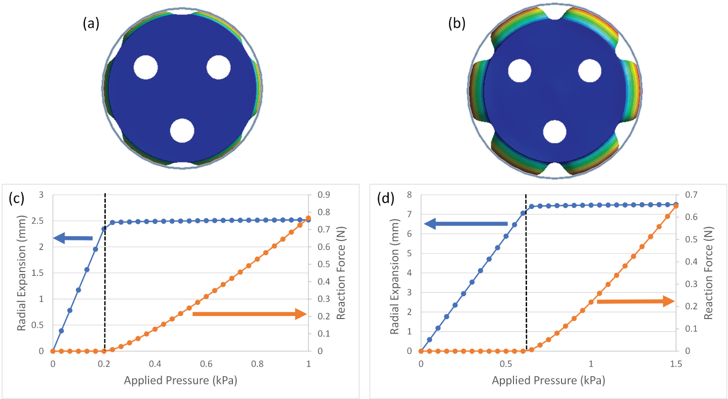
The simulation was a static structural simulation. The equations formed a sparse symmetric globally assembled matrix. The solver was iterative using a full Newton-Raphson procedure. The pressure was ramped linearly to a maximum in 30 sub steps. The contact force between the RECM and the inner surface of the pipe was defined as the radial contact pressure integrated over the area of all elements on the RECM in contact with the pipe (defined as elements with a contact status of either sticking or sliding). Results for pipes with internal diameters of both 75 mm and 85 mm are shown in Figure 13. As expected, the thin external walls of the RECM expand radially with pressure until contact with the inner pipe wall is made. For pipes with an internal diameter of 75 mm (hence maximum radial expansion of 2.5 mm), contact was made when an internal pressure of 0.2 kPa was applied to the RECM. For pipes with an internal diameter of 85 mm (hence maximum radial expansion of 7.5 mm), this was 0.67 kPa. As pressure is increased beyond these values, the maximum radial expansion is restricted by the pipe wall, but the cavities still expand tangentially increasing the contact area between the RECM and the pipe wall. The reaction force increases monotonically with pressure.
Horizontal locomotion
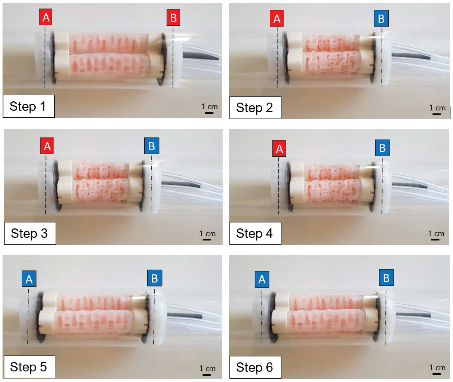
Figure 14 illustrates the complete locomotion cycle of the soft robot in a pipeline with internal diameter of 74 mm. As the cycle proceeds, the initial positions of the front and rear sections (A and B, respectively), are underlined in Red while the new advanced positions assumed are represented in Blue (A' and B').
In Step 1, the only component actuated was the RECM in the front, which applied a grip on the pipe wall. From Step 1 to Step 2, vacuum was applied in all three VAMPs simultaneously, contracting the robot of 36 mm and allowing the rear section to move forward. In Step 3 the rear section of the robot expanded and in Step 4 the front one deflated. By applying the same pressure in the robotic muscle, the VAMPs push the front section of the robot forward (Step 5). The cycle terminates in Step 6 when the front section's actuator is inflated again. The test showed that the soft robot was able to successfully travel the full length of the pipeline. It was noticed that since most of the components were silicone, a friction with the pipe was created when the robot was trying to push itself forward, marginally constraining the elongation of the robot.
Vertical locomotion
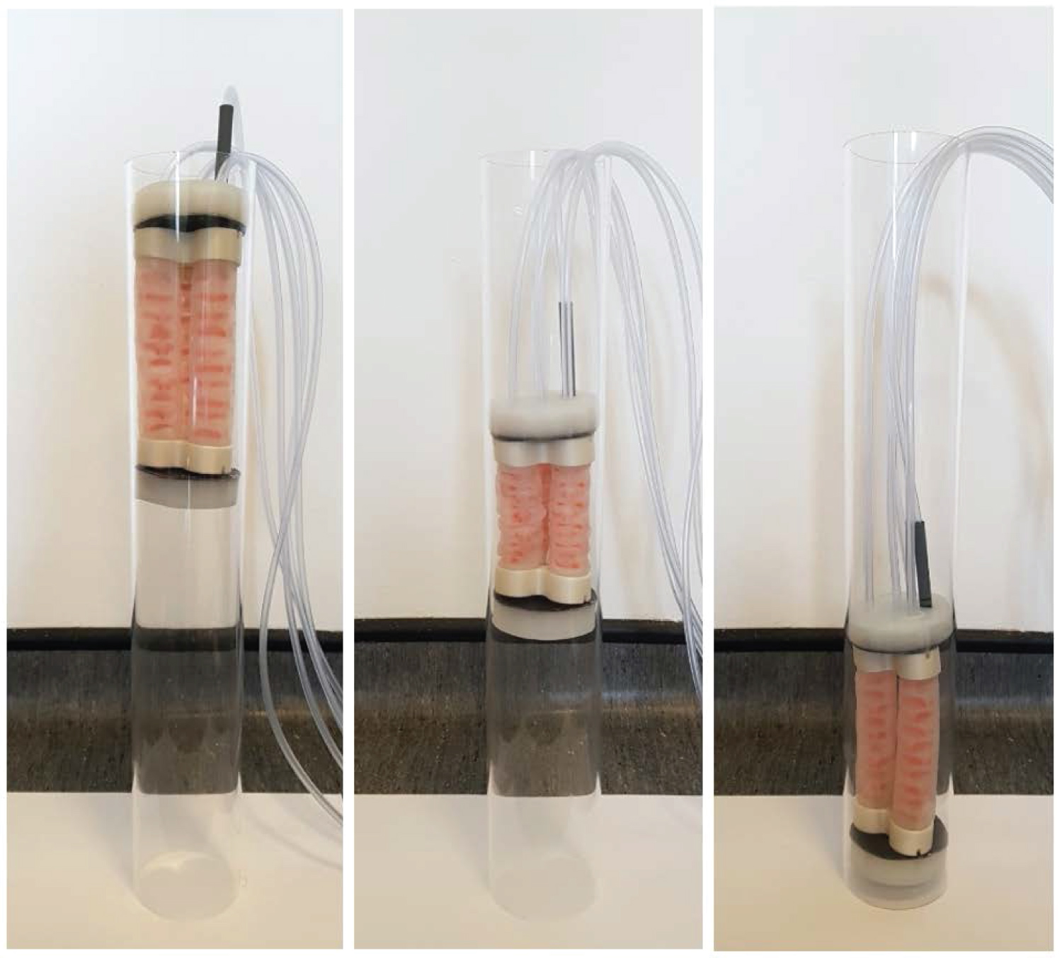
The bidirectional locomotion allowed the robot to move downwards and upwards without the need to physically turn the device upside-down (Figure 15). When moving downwards, the elasticity of the robot allowed the device to elongate slightly more than the horizontal test (i.e. > 36 mm) and the gravity reduced the frictional forces between the actuators and the pipe wall. The upward locomotion of the robot resulted to be the least efficient, since the soft robot had to overcome both gravity and friction. Although the overall weight of the robot was 343 g, it did not show any difficulty in lifting its entire body.
In both upwards and downwards locomotion, the expandable actuators at the front and rear section showed to be able to provide a firm grip on the pipe to prevent the robot from falling. The distance covered in each cycle in the two directions was 37 ± 2 mm when moving downwards, and 30 ± 2 mm when travelling upwards. This difference was caused by the elasticity of the actuators which were compressed due to gravity when moving upwards.
Active bending
There are multiple designs of prehensile soft robotics for a range of applications that can actively bend, see [13] for examples. Most soft pipe crawling robots, however, are designed for locomotion and don't actively bend, but instead conform to the shape of the pipe using the robot's inherent compliance to move around corners [23]. For many scenarios this is acceptable as the robot has a single route to follow which is defined and constrained by the pipe. However, in scenarios where this is not true, i.e. at junctions and ports, it is necessary to actively direct the front end of the robot in the desired direction, which may not be the direction that the robot will tend to move naturally. Compared to existing soft robots such as [11,12] and [23], the robot presented here can actively control the pressure applied on the wall while still being able to bend its body. This design allows for the direction of the front end of the actuator to be actively specified through independent control of the three parallel VAMPs.
During locomotion of the robot through a straight section of pipe, as demonstrated in the previous section, the pressure applied to all three VAMPs in the middle section of the robot is the same. Active bending is achieved by controlling the VAMPs independently. Specifically, the bend angle of the robot can be controlled by applying a vacuum to either one or two VAMPS independently.
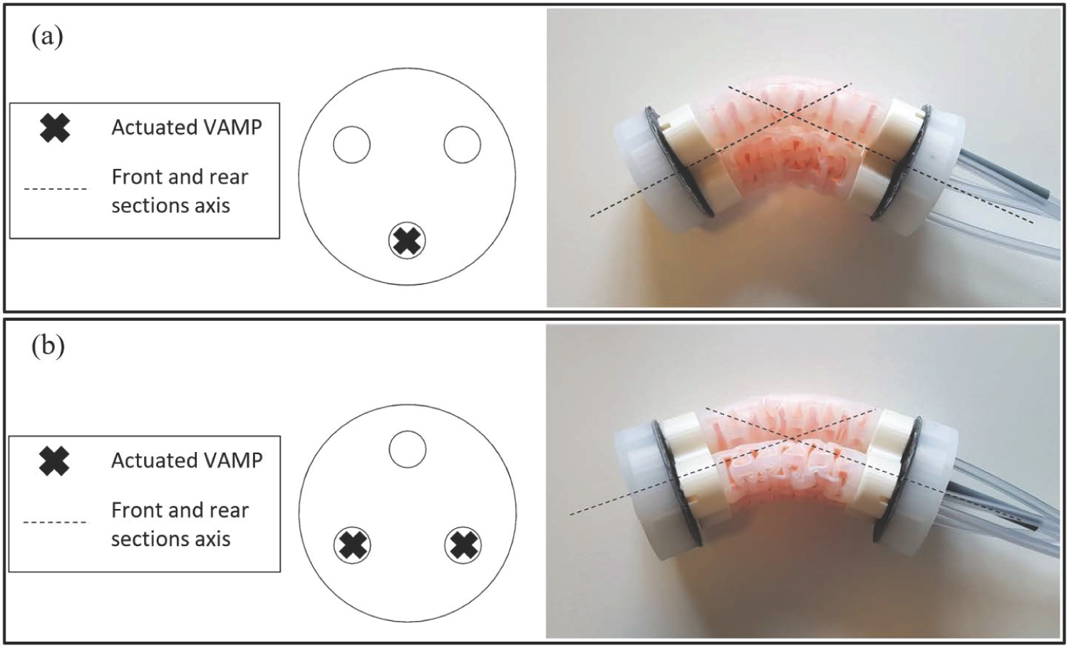
In Figure 16a, the bend is achieved by applying a vacuum to only one VAMP while keeping the other two inflated at atmospheric pressure. The deflection achieved was measured to be 35 ± 1° from its straight position. Figure 16b shows the bending obtained when actuating two of the three VAMPs and the deflection obtained in this test was 40 ± 1°. It is worth noting that by alternating between 1 and 2 contracted VAMPs, it is possible to exploit the three actuators to steer the robot in six different directions with a difference in orientation of 60° about the central axis of the robot.
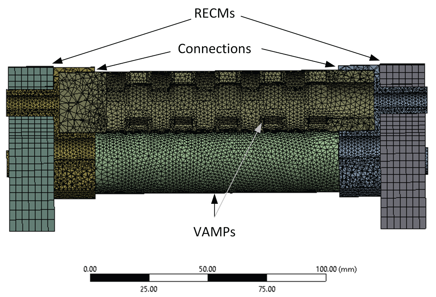
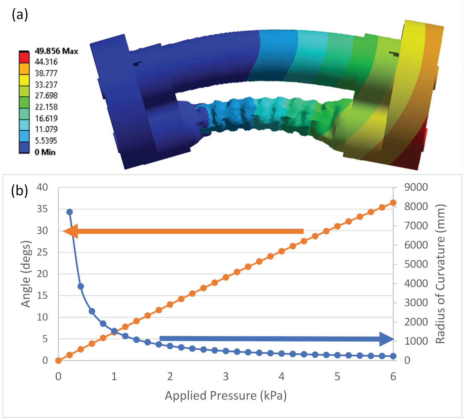
The bending of the robot was simulated using FEA in ANSYS 2020 R2 using a static structural formulation. In this simulation, the robot consisted of three parallel VAMPs, assembled with two end connectors (see Figure 4) and two RECMs (see Figure 3) to form a complete system. The internal structure of the RECMs was simplified to remove the internal cavities to reduce element count. The connectors were defined as PLA (elastic modulus 2.3 GPa, Poisson's ratio 0.3). The other components were defined as Ecoflex (elastic modulus 66 kPa, Poisson's ratio 0.48). The mesh is shown in Figure 17. There were 114,236 elements, consisting of 67,417 SOLID186/SOLID187 elements and 46,819 CONTA174/TARGE170 elements. Contact between the VAMPs and the RECMs and the connectors were defined as bonded. Self-contact with the internal and the external faces of the VAMP respectively were defined as rough and symmetric with small sliding allowed. Automatic bisection was used to predict changes in contact. The contact algorithm was the augmented Lagrange method with contact detection at the Gauss integration points. The equation solver was sparse, with the globally assembled matrix being symmetric. An iterative solver with a full Newton-Raphson procedure was used.
To demonstrate the effects of bending when one VAMP is independently deflated, the left-hand face of the RECM on the left was fixed in position and orientation and the pressure on the internal cavity of one of the VAMPs was ramped between 0 to 6 kPa below atmospheric pressure in 30 sub steps. All other surfaces were maintained at atmospheric pressure. As can be seen in Figure 18, the actuator is initially straight with an infinite radius of curvature and bends in a manner consistent with that shown in Figure 16 when the pressure is reduced, deflating the VAMP. Here, the angle of direction is defined as the angle the plane coincident with the right-hand face on the right hand RECM makes with the plane coincident with the fixed face on the opposite side. The radius of curvature is defined as the distance from the original central axis of the undeformed robot at the point it meets the fixed plane to the line where the fixed plane meets the plane on the right-hand side. As can be seen in Figure 18, an angle of 36° is made when a pressure of 6 kPa below the external pressure was applied to the internal cavity of one VAMP. It can also be seen that the relationship between pressure and angle of direction is almost, but not quite linear. If a linear relationship is assumed, the gradient can be taken as 6.24°/kPa, with a maximum error of ± 1° over the range of 0-6 kPa. However, a quadratic relationship of the form: Angle = -0.102 P2 + 6.71 P, where P is the pressure below atmospheric pressure, is more accurate with an error less than 10-4° over the range of 0-6 kPa.
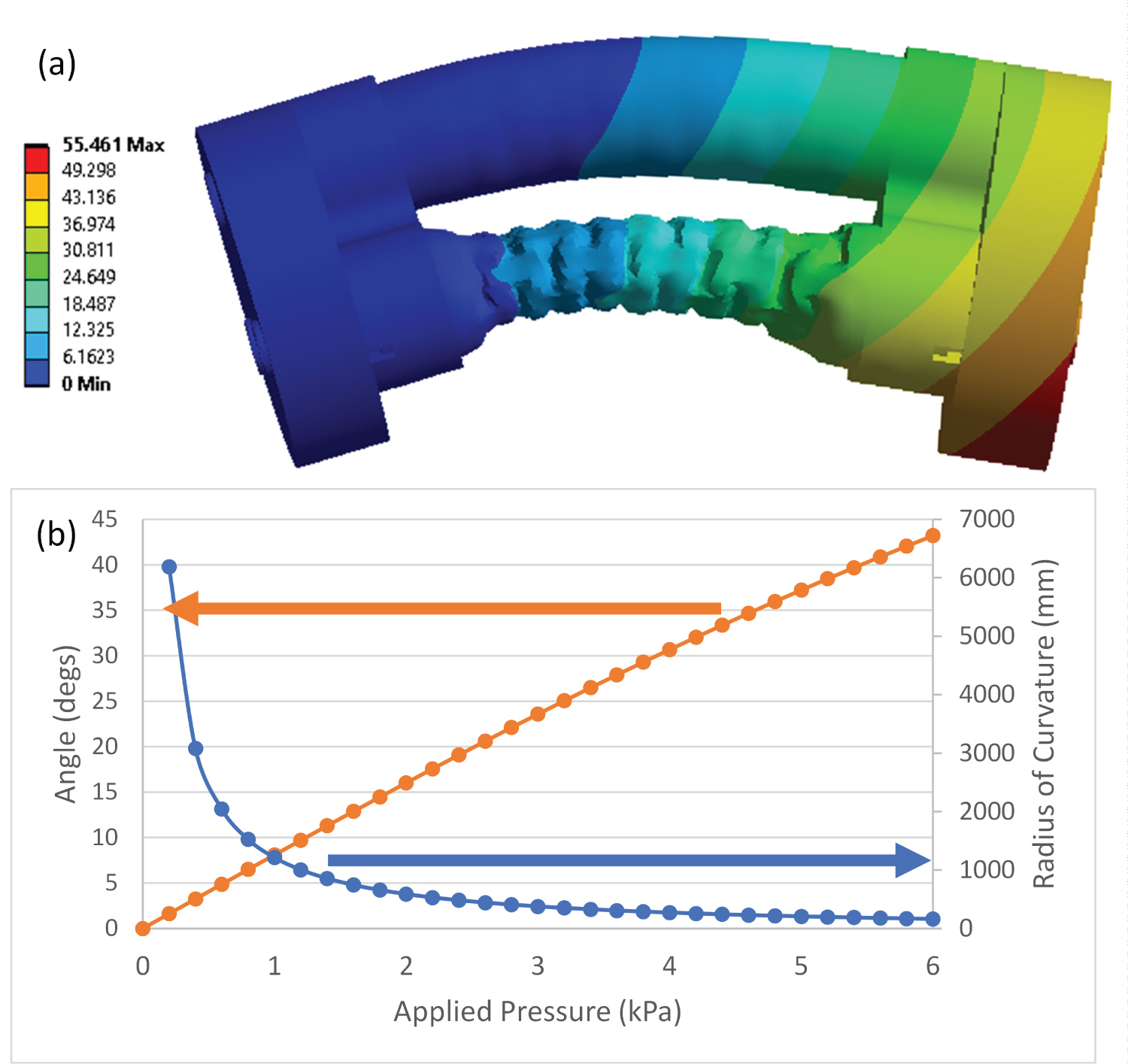
To test the effects of deflating two VAMPs, the simulation was repeated with mostly the same settings as described above. The difference in this case was that the pressure on the internal cavity of two of the VAMPs was ramped between 0 to 6 kPa below atmospheric pressure. As seen in Figure 19, the relationship between the angle of direction and applied pressure is even more distinctly quadratic in nature as: Angle = -0.205 P2 + 8.46 P, where P is the pressure below atmospheric pressure, with an error less than 10-4° over the range of 0-6 kPa. The maximum angle of direction was calculated to be 43°. It can also be seen that the deflection is greater when two VAMPs are actuated rather than one, which is to be expected and is consistent with that observed experimentally.
In a real application, such as traversing a pipe network in order to position inspection equipment or similar, it is expected that the system proposed here will form part of a larger robot configuration, perhaps formed of a number of hybrid soft/rigid modules that carry instrumentation and other control elements. In this sort of scenario, it is envisaged that there will be two or more modules comprised of the actuation system presented here along the length of the robot forming something akin in nature to a train, with different actuation modules providing the locomotion and others directing. By integrating the proposed design, an operator will have the ability to actively choose which direction the robot is to travel in allowing the navigation of complex unstructured pipe networks. This is to be the basis of future work.
Conclusion
This paper presents a new design of continuum soft inspection robot for pipelines, incorporating muscle-inspired actuators and expandable soft robotic components. By implementing an inchworm technique, it is possible to successfully enable the locomotion of the robot through pipelines, including those with bends and junctions. The robot consists of five soft actuators. These actuators include three parallel cylindrical VAMPs that contract axially, and two RECMs that expand radially placed at the front and rear of the robot. The VAMPs have an embedded bio-inspired structure which allows the motion and direction of the robot to be controlled. The individual VAMPs were shown to be able to contract its longitudinal length (nominally 129 mm) up to 28% and lift up to 150 g, without significant anomalous deformation. The maximum dilatation of the current dimensions of the RECM from its equilibrium point was 9 mm, which allows this design to transverse pipes with diameters 71-88 mm, which was experimentally verified in a straight pipe with a diameter of 74 mm in both vertical and horizontal configurations. The design should be scalable to other pipe diameters, although this hasn't been shown. Both actuators also demonstrated the ability to expand and contract linearly under changes of pressure. This characteristic is preferred because it allows to easily predict the actuator's behavior when controlled by a human operator and allows many future potential applications (e.g. rehabilitation devices or bio-inspired systems). The robot also experimentally demonstrated the ability to actively bend up to 40°. Active bending is achievable in six directions orientated 60° about the axis of the robot through simple activation of single or two VAMPs, allowing navigation in pipelines that present bends and junctions. The current control system was manual. The active bending during locomotion requires a more sophisticated, albeit quite standard, control system comprised of standard pneumatic control elements and an imaging system to map the inside of the pipe. This work is focused on the bio-inspired design of the actuators, and development of this control system is outside its scope.
Funding
Z.J.H. and D.C. acknowledge financial support and access to resources from the Engineering Department at Lancaster University.
References
- Iida F, Laschi C (2011) Soft robotics: Challenges and perspectives. Procedia Computer Science 7: 99-102.
- Manti M, Cacucciolo V, Cianchetti M (2016) Stiffening in soft robotics: A review of the state of the art. IEEE Robotics & Automation Magazine 23: 93-106.
- Chen F, Wang MY (2020) Design optimization of soft robots: A review of the state of the art. IEEE Robotics & Automation Magazine 27: 27-43.
- Seok S, Onal CD, Wood R, et al. (2010) Peristaltic locomotion with antagonistic actuators in soft robotics. IEEE International Conference on Robotics and Automation.
- Milana E, Van RCK, Dehaerne E, et al. (2020) EELWORM: A bioinspired multimodal amphibious soft robot. 2020 3rd IEEE International Conference on Soft Robotics (RoboSoft), New Haven, USA.
- Park T, Cha Y (2019) Soft mobile robot inspired by animal-like running motion. Scientific Reports 9: 1-9.
- Trebuna F, Virgala I, Pástor M, et al. (2016) An inspection of pipe by snake robot. International Journal of Advanced Robotic Systems, 1-12.
- Kwon YS, Byung JY (2012) Design and motion planning of a two-module collaborative indoor pipeline inspection robot. IEEE Transactions on Robotics 28: 681-696.
- Gargade AA, Ohol S (2016) Development of in-pipe inspection robot. IOSR Journal of Mechanical and Civil Engineering 13: 64-72.
- Nayak A, Pradhan S (2014) Design of a new in-pipe inspection robot. Procedia Engineering 97: 2081-2091.
- Adams W, Sridar S, Thalman C, et al. (2018) Water pipe robot utilizing soft inflatable actuators. IEEE International Conference on Soft Robotics (RoboSoft), 321-326.
- Jiao Z, Ji C, Zou J, et al. (2018) Vacuum-powered soft pneumatic twisting actuators to empower new capabilities for soft robots. Advanced Materials Technologies 4.
- Zhang Y, Xu J, Wang W (2018) Kinematics and force analysis of flexible screw mechanism for a worm robot. Journal of Mechanisms and Robotics.
- Walker ID (2013) Continuous backbone "continuum" robot manipulators. ISRN Robotics 2013: 19.
- Walker ID, Carreras C, McDonnell R, et al. (2006) Extension versus bending for continuum robots. International Journal of Advanced Robotic Systems.
- Teeple CB, Koutros TN, Graule MA, et al. (2020) Multi-segment soft robotic fingers enable robust precision grasping. The International Journal of Robotics Research.
- Xiang C, Guo J, Rossiter J (2018) Continuum EA: A soft continuum electroadhesive manipulator. 2018 IEEE International Conference on Robotics and Biomimetics.
- Godage S, Nanayakkara T, Caldwell DG (2012) Locomotion with continuum limbs. IEEE/RSJ International Conference on Intelligent Robots and Systems.
- Calisti M, Picardi G, Laschi C (2017) Fundamentals of soft robot locomotion. J R Soc Interface.
- Zhang L, Qiang H, Wenkang W, et al. (2020) Design and characterization of a soft vacuum-actuated rotary actuator. Journal of Mechanisms and Robotics 12.
- Cho KH, Ho MK, Youngeun K, et al. (2019) Multiple inputs-single accumulated output mechanism for soft linear actuators. Journal of Mechanisms and Robotics 11.
- Ashwin KP, Ashitava G (2019) A soft-robotic end-effector for independently actuating endoscopic catheters. Journal of Mechanisms and Robotics 11.
- Zhang Z, Wang X, Wang S, et al. (2019) Design and modeling of a parallel-pipe-crawling pneumatic soft robot. IEEE Access 7: 134301-134317.
- Laschi C, Cianchetti M, Mazzolai B, et al. (2012) Soft robot arm inspired by the octopus. Advanced Robotics 26: 709-727.
- Jan F, Noh Y, Macias M, et al. (2018) Bio-inspired octopus robot based on novel soft fluidic actuator. 2018 IEEE International Conference on Robotics and Automation.
- Yang D, Verma M, So JH, et al. (2016) Buckling pneumatic linear actuators inspired by muscle. Advanced Materials Technologies.
- Manuel S, Jakob AF, Lucas P, et al. (2018) 3D printing of robotic soft actuators with programmable bioinspired architectures. Nature Communications 9: 878.
- Liu Y, Zhuang G, Shangkui Y, et al. (2019) Elephant's trunk robot: An extremely versatile under-actuated continuum robot driven by a single motor. Journal of Mechanisms and Robotics.
- Calderon AA, Ugalde JC, Zagal JC, et al. (2016) Design, fabrication and control of a multi-material-multi-actuator soft robot inspired by burrowing worms. 2016 IEEE International Conference on Robotics and Biomimetics.
- Ning J, Ti C, Liu Y (2017) Inchworm inspired pneumatic soft robot based on friction hysteresis. Journal of Robotics and Automation 1: 54-63.
- Trivedi D, Rahn CD, Kier MW, et al. (2008) Soft robotics: Biological inspiration, state of the art, and future research. Applied Bionics and Biomechanics 5: 99-117.
Corresponding Author
David Cheneler, Department of Engineering, Lancaster University, Bailrigg, Lancaster, LA1 4YW, UK.
Copyright
© 2021 Hu ZJ, et al. This is an open-access article distributed under the terms of the Creative Commons Attribution License, which permits unrestricted use, distribution, and reproduction in any medium, provided the original author and source are credited.