Inchworm Inspired Pneumatic Soft Robot Based on Friction Hysteresis
Abstract
In this paper, we present an inchworm-inspired pneumatic soft robot that requires only one degree of freedom control to generate continuous linear locomotion on various surfaces. The locomotion is realized by the friction hysteresis resulting from the deformability of one robot leg, which is passively enabled by the robot design. The inchworm robot is made of a single material, has a single degree of freedom, and only requires the air pressure as a single-channel control signal to realize continuous locomotion. The length of robot can be shrunk down to 40 mm while maintaining the locomotion. In addition, by adding a separate air cavity in each leg, the friction hysteresis can be turned on and off, allowing the motion direction of the robot to be controllable. The inchworm soft robot can serve as a versatile platform on which various tasks can be fulfilled, such as chemical sensing with embedded sensors, cargo delivery in hazardous environments, and education on soft creatures and soft robot design.
Keywords
Inchworm soft robot, Passive friction hysteresis, Deformable legs, Pneumatic actuation
Introduction
Nature always provides simple, energy efficient and effective designs. Biomimetics allows the design merits of the nature to benefit manmade mechanisms. Over the last few decades, mechanical rigid robots, which mimic bone and joint structures of animals, have made considerable progress to liberate human from heavy manual works and hazardous environments. However, most of creatures in nature utilize flexibility to adapt surrounding environments [1], which inspire the development of soft robotics. Soft robots are built with soft, deformable, and continuum materials. They have a number of advantages such as flexibility, adaptability, and low cost.
In nature, locomotion of peristaltic worms such as caterpillar and earthworm are particularly interesting. Inspired by nature, worm-like robots such as peristaltic robots and inchworm robots have recently attracted interests because of their capability of adapting dynamically changing environments.
The locomotion of peristaltic worms such as caterpillars and earthworms is realized by sequentially activating multiple body segments in contraction and expansion motions [2]. A variety of caterpillar-like soft robots have been demonstrated. A 3D printed caterpillar shaped soft robot (PS robot) has been demonstrated to realize similar locomotion [3]. Each leg is composed of two parts with different friction coefficients. When a leg is electrically heated, the Shape Memory Alloy (SMA) embedded in the body bends the leg, resulting in different parts contacting the ground which varies the friction. Inching and crawling locomotion is realized when the leg friction and the body bending are controlled in the right sequence. The PS robot had 2 Degrees of Freedom (DOFs) and it took 0.6 second for each motion cycle. Recently, a Softworm [4] was developed to realize similar locomotion with a motor driven tendon system instead of SMA. The motor-tendon driving system allows fast locomotion speed of around 0.56 body length per second. Another caterpillar-like soft robot, named as GoQBot [5], has been demonstrated with both crawling and rolling locomotion. Crawling is realized similar with the PS robot. However, if the body is bent suddenly with large enough amplitude, the GoQBot can roll over its hammer-shaped head. GoQBot had a length of around 10 cm and was capable of making the rolling motion range up to 25 cm with initial accelerating speed over 0.5 m/s. A caterpillar-like climbing robot [6] is made of multiple rigid parts connected with joints. The locomotion is achieved by bending various joints throughout the body in sequence to propagate the hump along the body. Similarly, a modular self-reconfigurable robot [7] is composed of 8 linked rigid modules. A Field-Programmable Gate Array (FPGA) processor is used to control each module. The locomotion is achieved by the propagation of body motion waves through the robot, from tail to head. An earthworm inspired mesh tube soft robot [8] was composed of spiral polymer fibers and radial and circular nitinol actuators. Elongation of the body is realized by radial contraction, resulting in forward locomotion. A peristaltic locomotion of 3.47 mm per second was demonstrated with a five-segment prototype.
Inchworms realize locomotion by alternating two kinds of stroke motions: longitudinal leg motions and omega-shaped body bending motions [9]. Soft robots inspired by this locomotion have also been developed. The locomotion of inchworm soft robots is always realized by anchor-pull and anchor-push motions. Compared with peristaltic robots, inchworm robots realize locomotion mainly by changing the friction coefficients of the two legs, while the body is bent with only one DOF. Omegabot is an inchworms-like robot that consists of multiple rigid segments connected with flexible joints [10]. Its first and last segments are partially covered by sticky silicone polymer layers, serving as two legs in contact with the ground. The friction coefficients of the two legs can be controlled in real time by the orientation of the legs. Linear locomotion can be realized by simultaneous control of body contraction and the leg friction coefficients. Each joint can be bent in two orthogonal directions to enable the robot to turn. Another inchworm-inspired soft robot [11] can adjust the leg friction coefficients by changing the shape of the legs. Linear locomotion is realized similarly with the Omegabot, except that the leg friction is controlled by the leg shape by the actuation of two short SMAs laterally embedded. A piezoelectrically driven inchworm robot [12] has been demonstrated to realize locomotion by a single unimorph actuator in the body. Comparison of the frictions at the two legs can be changed by simply bending up and bending down the body, thanks to the inclination of two specially designed legs. This design allows inching locomotion to be realized with one DOF, and the frictions of the legs are adjusted in a passive manner. A capsule robot [13] is developed to realize inching locomotion by a pair of clamps. The biomimetic submillimeter clamps can slide forward on the substrate, while the backward motion is prohibited because the clamps will grip the substrate. These passive clamping and releasing functions allow the capsule to be moved forward during the locomotion.
There are still challenges for existing worm-like soft robots. The above mentioned designs are composed of multiple materials and multiple parts, which require relatively complex fabrication and assembly processes. Moreover, most of the above mentioned designs [2-10,12] require multiple DOFs, and hence require relatively complex motion control in sequence. Reducing the DOFs is also desired in order to reduce the soft robot size and to decrease the time period for each locomotion cycle.
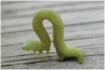
In this paper, we design and demonstrate a pneumatic inchworm soft robot, inspired by geometer moth larvae shown in Figure 1 that is capable of generating continuous and robust inching gaits. The locomotion is realized because the friction coefficient of one leg exhibits orientation-dependent hysteresis, which is enabled by the design of the shape of the leg. The inchworm robot has a simple design and small size (as small as 40 mm long), and is built by the soft lithography method with low-cost silicon rubber materials. The whole fabrication process of our inchworm robot only requires around 4 hours, and the robot can potentially be batch fabricated. A fast locomotion cycle of 0.4 second has been demonstrated. The inchworm robot can potentially be used in hazardous situation to carry weights and perform chemical sensing.
Inchworm Inspired Soft Robot
Design
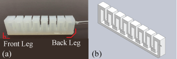
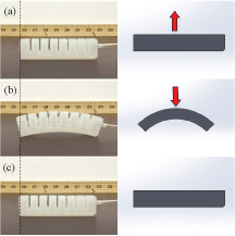
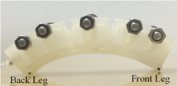
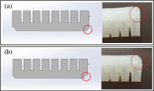
The inchworm robot is made by a readily available soft silicon rubber material similar with that used in previous works [14]. The robot consists of a saw-tooth shaped body with an air cavity inside and a flat bottom, as shown in Figure 2. The saw-tooth profile design [15] on top allows the inchworm robot to bend up when pressurized and bend down when the pressure is released. A vented screw and PVC tube, serving as air inlet and outlet, are connected to the air cavity through the backside wall. An air pump (syringe) was used to increase or decrease the pressure in the air cavity in order to drive the locomotion. The regular inchworm robot is 98 mm long, 17 mm tall, and 25 mm wide. The front bottom has a sharp edge, while the back bottom edge is chamfered. These shapes are designed such that the front leg exhibits a different friction coefficient when the robot bends up and down, which allows the locomotion to be realized. More details will be discussed in Sections 2.3 and 2.4. In the rest of this paper, the front and back bottoms are referred to as front and back legs, because the locomotion is realized by their contacts with the ground.
Fabrication
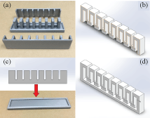
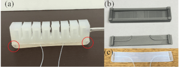
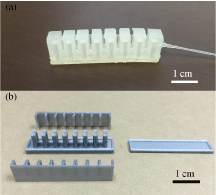
Soft lithography was used to fabricate inchworm robot. The saw-tooth top and flat bottom of the robot were fabricated separately by molding processes, and they were combined to complete the fabrication process, as shown in Figure 3. The molds were designed by SolidWorks software and fabricated by a 3D printer (Ultimaker 2, Ultimaker) with the material of Polylactic Acid (PLA).
We started the fabrication process by mixing the two liquid components of the silicone rubber (Dragon Skin 30, from Reynold Advanced Materials, Boston) in a small plastic cup. The mixture was then put inside a vacuum chamber to remove air bubbles for approximate 40 minutes. We poured the degassed liquid silicone rubber into assembled molds shown in Figure 3a. An extra degassing process might be necessary to remove air bubbles completely after pouring silicone rubber into the molds. The filled molds were put on a hot plate at 40 ℃ for around 3 hours to cure. After the cured saw-tooth top of the robot (Figure 3b) was separated from the molds, one vented screw and one nut were mounted through the side wall to serve as both an air inlet and outlet. A flat rectangular bottom layer was fabricated separately with same procedures and same material but different mold, as shown in Figure 3c. Immediately after the liquid rubber filled the bottom mold, the cured saw-tooth top was placed on top. The top and bottom of the robot were hence bonded together after the bottom was fully cured, as shown in Figure 3d. At this point, both the front and back legs were sharp-angled. We cut the back leg by a blade to obtain a chamfered edge with an inclination angle of about 45 degrees as shown in Figure 2, which will eliminate the friction hysteresis of the back leg (detailed in Sections 2.3). We finished the fabrication process by connecting a 2 mm inner diameter PVC tube to the vented screw by using general purpose epoxy glue.
Friction hysteresis and locomotion mechanism
The uniqueness of our inchworm robot is that the locomotion is realized by the friction hysteresis of the front leg, which is enabled passively by the leg design. In this section, we will discuss in detail how our design enables this friction hysteresis, as well as the experimental and simulation results that confirm this design enabled locomotion mechanism.
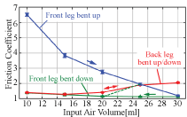
The inchworm robot is designed such that there is a frictional difference between its two legs. In addition, there is a design-enabled hysteresis in the friction coefficient of the sharp-angled front leg, while no similar hysteresis exists for the chamfered back leg. When the robot is pressurized and bends up, the front leg has a larger friction than the back leg, resulting in the front leg fixed and the back leg sliding forward, as shown in Figure 4a. When the pressure is released and the robot bends down, the front leg has a smaller friction than the back leg, causing the front leg to slide forward and back leg to be fixed, as shown in Figure 4b. The linear locomotion is thus achieved by continuously bending the robot up and down. More detailed results of the locomotion will be shown in Section 2.4.
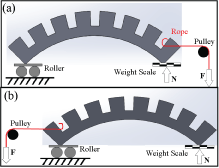
To confirm the design enabled friction hysteresis, we measured coefficients of the friction for both front and back legs at different bending angles. The experimental setup is shown in Figure 5. The leg to be measured was placed on the smooth aluminum surface of a scale, while the other leg was supported by a roller. A force F was applied on the robot horizontally via a pulley system. The maximum value of F (Fmax) that kept the robot stationary was recorded, and the normal force N was measured directly by the scale. Because the friction of the roller was negligible, the friction coefficient of measured leg was found by Fmax/N.
In the experiment, we varied the input air volume from 10 ml to 30 ml to change the bending of the robot. The dependence of the friction coefficients of both legs on the input air volume is shown in Figure 6. At each input air volume, the normal force and friction were measured for three times. The mean values are plotted in Figure 6, and the uncertainty was obtained by the standard deviation of the three measurements. It can be clearly seen that the hysteresis of friction coefficient only exists in the front leg, but not in the back leg. As a result, the friction of front leg is larger (smaller) than the back leg when the robot is bent up (down), realizing the locomotion described in Figure 4.
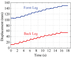
It is noted that, at a high input air volume (> 25 ml), the front leg might slide no matter which direction the robot bends, because the back leg always has a higher friction. For all the results in the rest of this paper, we confine the maximum input air volume to be between 20 ml and 25 ml, which will prevent the front leg from sliding during the bending up section. However, the back leg will slide backward slightly in the beginning of the bending down section (the green dashed line in Figure 6). This understanding will be verified in the results shown in Figure 7 and discussed in Section 2.4.
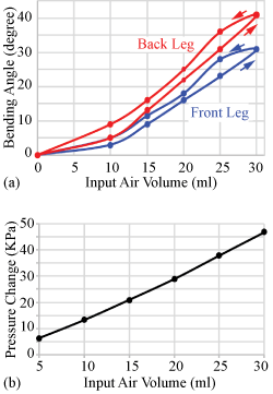
In addition to the friction of the front leg, the bending angles also exhibited hysteresis. The bending angles were measured from the camera images of the robot, and the air volume was measured by reading the ticks on the syringe. The experimentally measured bending angles of both legs at various input air volumes are shown in Figure 8. The measurement uncertainties (not shown) of the bending angle and input air volume are 1° and 0.5 ml, respectively. The source of the uncertainties of the bending angle is the resolution of the angle measurements, and the source of the air volume uncertainties is the reading error of the ticks. At any given input air volume, the bending angles of both legs were smaller during bending up than those during bending down.
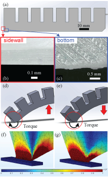
Although the friction hysteresis of the sharp-edged front leg has been confirmed by the experimental measurements, we would like to discuss the mechanism of how our design enables this friction hysteresis and hence the locomotion. The friction hysteresis can be understood by the dependence of the robot-ground contact surface on the robot bending direction. As shown in the schematics in Figure 9d and Figure 9e, when the robot bends up (down), the torque applied by the ground is clockwise (counter-clockwise), due to the deformation of the front leg. This different deformation results in different robot surfaces in contact with the ground: sidewall when bent up and bottom when bent down. The friction hysteresis is hence caused by the different roughness of the robot sidewall and bottom, as shown in Figure 9a, Figure 9b and Figure 9c.
This mechanism is confirmed with numerical simulation carried out with the Comsol software. The material properties of the inchworm robot used in the simulation include a density of 2000 kg/m3 and a Poisson's ratio of 0.48, both of which were found in the Dragon Skin 30 information sheet provided by the commercial supplier, and an elastic modulus of 0.781 MPa, which was experimentally measured with a Dynamic Mechanical Analysis (DMA) tensile test machine. In Comsol, the ground, which is below the front leg, was moved to the left (right) to imitate the situation when the robot bends up (down), as shown in Figure 9f and Figure 9g. The calculated deformation and stress distribution on the front leg are shown in Figure 9f and Figure 9g. The simulated deformation results confirm the understanding of the locomotion mechanism and the design of the robot front leg. Specifically, due to the friction and torque applied by the ground to the front leg, the ground contacting surface of the robot changes when the bending direction changes, resulting in friction hysteresis of the front leg during the locomotion. To facilitate this locomotion mechanism, the front leg should be designed with a deformable corner (such as a sharp edge) and different surface roughness on the sidewall and bottom.
The main reason of the front leg friction hysteresis is the difference in surface roughness on the bottom and on the sidewall of the sharp-edged front leg. In all our 3D printed molds, the sidewalls are smoother than the bottom surfaces, due to the layer-by-layer 3D printing technique. As a result, the sidewall of the front leg is smoother than the bottom surface, as shown in Figure 9a, Figure 9b and Figure 9c. Thanks to the sharp-edged design, the contact surface of the front leg with the ground is dependent on the direction of the bending. When the robot is bent up, the rough bottom surface of the front leg contacts the ground, resulting in a large friction coefficient, as shown in Figure 9d and Figure 9f. When the robot is bent down, the smooth sidewall contacts the ground, resulting in a small friction coefficient, as shown in Figure 9e and Figure 9g.
By comparison, the back leg is designed to have a chamfered surface that is much larger and stiffer as well than the sharp edge of the front leg. Therefore, the contact surface of the back leg remains the chamfered surface and is not dependent on the bending direction, resulting in no hysteresis of the friction coefficient.
Results and discussion
A full cycle of the locomotion of the inchworm robot on a wood surface was recorded in the experiment and is shown in Figure 10. The input air volume was increased and decreased through a connected PVC tube and a vented screw (mounted on caterpillar robot body) to drive the locomotion. The inchworm robot demonstrated a locomotion of around 2 mm per cycle and a period of around 0.4 second. This short period is a result of only one DOF and the simple driving mechanism. In addition, our model itself can serve as a pneumatic actuator [15], such as gripping mechanisms and artificial muscles.
To understand the locomotion of inchworm robot quantitatively, an experimentally recorded video of the locomotion was processed using MATLAB codes. The robot moved with a speed of 2.2 mm/s on an acrylic plate in this experiment. The obtained time-dependent displacements of both legs are shown in Figure 7. It can be seen that continuous and repeatable motion patterns were realized by both legs. The front and back legs were alternatively moved forward, which realized a predictable and robust locomotion toward one direction. As described in Section 2.3 and Figure 6, the back leg slid forward during the bending up section, but slid backward slightly in the beginning of the bending down section. This backward motion after every forward motion of the back leg can be clearly seen in Figure 7.
Although the requirement for a continuous air source is a frequent problem for pneumatic soft robots, the high flexibility of both the inchworm robot body and that of the pipes between the air source and the robot allows it to reach deep in a confined space, which rigid robots cannot do. The potential applications of the inchworm robots include endoscopes, targeted medicine release devices, as well as educational purposes.
More, inchworm robot demonstrated a good adaptability of walking on different surfaces and carrying weights. The inchworm robot has been demonstrated to walk on various surfaces, including metal, plastic, wood, and paper. As shown in Figure 11, the inchworm robot can carry a weight of 50 grams while still realizing proper locomotion on acrylic plastic, aluminum alloy (not shown), and paper (not shown) surfaces. However, it was difficult for the inchworm robot to crawl on surfaces with water, because the friction hysteresis of its two legs were not reserved on wet surfaces.
Inchworm Robot with Deformable Legs
So far, we have realized the single-direction locomotion of the inchworm robot which relies on the friction hysteresis and the deformability of the sharp-edged front leg. It is beneficial if the inchworm robot can move in both forward and backward directions. Therefore, we designed an advanced inchworm robot which had an additional air cavity in each leg, as shown in Figure 12a. Compared to the legs of the inchworm robot (in Section 2) that are solid pieces with the geometry and texture differences, each leg of the advanced inchworm robot can be deformed and can switch between convex and concave profiles when the pressure in the air cavity is increased and decreased, respectively. The convex leg profile demonstrates friction hysteresis, while the concave does not. By switching the convex/concave profiles of the two legs, we can change the locomotion direction. The size of the advanced inchworm robot is 98 mm long, 20 mm tall, and 25 mm wide.
The fabrication process of the inchworm robot is similar with that discussed in Section 2.2. The only difference is the fabrication of the bottom layer, where the two separate air cavities are embedded in the two legs. As shown in Figure 12b and Figure 12c, the 3D printed molds are slightly modified to include the air cavities as well as the grooves on the surface to run the two tubes that connects the two air cavities.
As shown in Figure 13, thanks to the deformable leg design, the friction hysteresis of each leg of the inchworm robot can be switched on and off in real time, bestowing for the capability of the robot to move in opposite directions in a controlled fashion (data not shown). Compared with the inchworm robot with only one air cavity (in Section 2), the robot discussed in this section can move in both forward and backward directions with a cost of two additional DOFs, although the robot size is about the same.
Small Inchworm Robot
The simple and effective design of the inchworm robot allows us to shrink down its size while maintaining the same fabrication process. The compact size, as well as the flexibility, of the inchworm robot is beneficial to realize locomotion where rigid robots are not suitable, especially in confined environments, and to achieve fine displacement resolution during the locomotion. We demonstrated an inchworm robot that was 40 mm long, 7 mm tall, and 11 mm wide, as shown in Figure 14. The robot has exactly the same design as the one shown in Figure 3, but with a smaller size. This small robot can realize similar locomotion with a step size of 1.5 mm and a time period of 0.5 second (data not shown). To the best of our knowledge, this is the smallest pneumatic soft robot so far that is capable of generating continuous and robust locomotion. The size of inchworm robot can be reduced even more with a better resolution of 3D printing or with other fabrication methods such as casting and excimer lamp bonding method [16].
Future Work
Due to only one DOF of the inchworm robots in Sections 2 and 4, the steering function has not been realized. To realize steering function, the air cavity inside the saw-tooth top can be separated into two independent parts, one on the left and the other on the right of the robot body. In this case, when one cavity pressurized and the other depressurized, the soft robot body will bend toward the depressurized side in order to make a turn. Moreover, a sub-mm sized inchworm soft robot can be realized with a similar design, if the molds are fabricated by photolithography. Both the steering and the sub-mm inchworm robots are under development.
Conclusion
In this work, we demonstrated inchworm pneumatic soft robots with air cavities that achieved continuous and robust linear locomotion. It is easy to fabricate, low-cost, and compact in size. The locomotion was realized by the friction hysteresis and the deformability of one leg, both of which are enabled by the design of the robot. The friction hysteresis has been experimentally verified and understood by both the friction coefficient measurements and numerical simulation. The robot can move on various surfaces and carry weights. To the best of our knowledge, this is the first single-cavity pneumatic soft robot that can achieve continuous locomotion. By adding a separate air cavity in each leg, the friction hysteresis of each leg can be switched on and off, allowing the robot to move in both directions. In addition, the robot length can be shrunk down to 40 mm, thanks to the simple design. The inchworm soft robot provides a versatile platform on which various sensors can be embedded, and can find potential applications such as sensing and cargo delivery in hazardous environments. The simple design and fabrication process also makes it ideal in education for students to better understand how soft creatures live and to inspire youth to design and create soft robots.
Acknowledgements
The author would like to acknowledge the Soft Robotics Toolkit website [17] for soft robot fabrication instructions.
References
- Trivedi D, Rahn CD, Kier WM, et al. (2008) Soft robotics: Biological inspiration, state of the art and future research. Applied Bionics and Biomechanics 5: 99-117.
- Quillin KJ (1999) Kinematic scaling of locomotion by hydrostatic animals: ontogeny of peristaltic crawling by the earthworm Lumbricus terrestris. J Exp Biol 202: 661-674.
- Umedachi T, Vikas V, Trimmer B (2013) Highly deformable 3-d printed soft robot generating inching and crawling locomotions with variable friction legs. Intelligent Robots and Systems, 4590-4595.
- Umedachi T, Vikas V, Trimmer BA (2016) Softworms: The design and control of non-pneumatic, 3D-printed, deformable robots. Bioinspir Biomim 11: 025001.
- Lin HT, Leisk GG, Trimmer B (2011) GoQBot: A caterpillar-inspired soft-bodied rolling robot. Bioinspir Biomim 6: 026007.
- Chen J, Wu J, Luo M, et al. (2014) A Knitro-based real-time locomotion method for imitating the caterpillar-like climbing strategy. Control & Automation (ICCA), 145-150.
- González-Gómez J, Aguayo E, Boemo E (2005) Locomotion of a modular worm-like robot using a FPGA-based embedded microblaze soft-processor. Climbing Walking Robots: Proceedings of the 7th International Conference CLAWAR 2004. Springer, 869-878.
- Seok S, Onal CD, Wood R, et al. (2010) Peristaltic locomotion with antagonistic actuators in soft robotics. IEEE International Conference on Robotics and Automation, 1228-1233.
- Wang W, Wang Y, Wang K, et al. (2008) Analysis of the kinematics of module climbing caterpillar robots. Advanced Intelligent Mechatronics, 84-89.
- Koh JS, Cho KJ (2009) Omegabot: Biomimetic inchworm robot using SMA coil actuator and smart composite microstructures (SCM). Robotics and Biomimetics (ROBIO), 1154-1159.
- Wang W, Lee JY, Rodrigue H, et al. (2014) Locomotion of inchworm-inspired robot made of smart soft composite (SSC). Bioinspir Biomim 9: 046006.
- Lobontiu N, Goldfarb M, Garcia E (2001) A piezoelectric-driven inchworm locomotion device. Mechanism and Machine Theory 36: 425-443.
- Kim B, Lee S, Park JH, et al. (2004) Inchworm-like microrobot for capsule endoscope. Robotics and Biomimetics, 458-463.
- Sun Y, Song YS, Paik J (2013) Characterization of silicone rubber based soft pneumatic actuators. Intelligent Robots and Systems (IROS), 4446-4453.
- Mosadegh B, Polygerinos P, Keplinger C, et al. (2014) Pneumatic networks for soft robotics that actuate rapidly. Advanced Functional Materials 24: 2163-2170.
- Ogura K, Wakimoto S, Suzumori K, et al. (2008) Micro pneumatic curling actuator-Nematode actuator. ROBIO, 462-467.
- Soft Robotics Toolkit.
Corresponding Author
Yuxiang Liu, Department of Mechanical Engineering, Worcester Polytechnic Institute, Worcester, MA 01609, USA.
Copyright
© 2017 Ning J, et al. This is an open-access article distributed under the terms of the Creative Commons Attribution License, which permits unrestricted use, distribution, and reproduction in any medium, provided the original author and source are credited.

