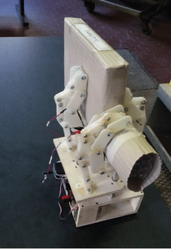
Virtual and Rapid Prototyping of an Underactuated Space end Effector
Abstract
A fast and reliable verification of an initial concept is an important need in the field of mechatronics. Usually, the steps for a successful design require multiple iterations involving a sequence of design phases-the initial one and several improvements-and the tests of the resulting prototypes, in a trial and error scheme. Now a day's software and hardware tools allow for a faster approach, in which the iterations between design and prototyping are by far reduced, even to just one in favorable situation. This work presents the design, manufacturing and testing of a robotic end effector for space applications, realized through virtual prototyping, followed by rapid prototyping realization. The first process allows realizing a mathematical model of the robotic system that, once all the simulations confirm the effectiveness of the design, can be directly used for the rapid prototyping by means of 3D printing. The workflow and the results of the process are described in detail in this paper, showing the qualitative and quantitative evaluation of the performance of both the virtual end effector and the actual physical robotic hand.
Keywords
Virtual prototyping, Rapid prototyping, Space end effectors
Introduction
Many future space operations will involve robotic devices for manipulation of orbiting targets. The goal could be to remove spent launcher's stages, to repair satellites, or to dock to other modules in order to form larger platforms [1]. The manipulators and its end effector must be purposely designed to face the special requirements imposed by the space environment. In fact, with respect to terrestrial robotic arms, both the target and the arm's base are unconstrained; the direct effect is a more difficult and less reliable grasp of the floating target.
A lot of research activity has been done both on the operations of the arm [2,3], and on the configuration that the end effector should have. Several examples of dexterous robotic hands have actually flown and an additional number of them are currently in the development phase. One of themost appealing applications is represented by the possibility to perform dexterous operations in order to help/substitute the astronauts' skills and reduce human extravehicular activities and related risks and costs. An example of this approach is given by NASA building and in-orbit testing of the ROBONAUT [4], as well as ESA funding the EUROBOT project [5]. Many of the projects falling into this class are intended to be accommodated onboard the ISS: the JAXA (Japan Aerospace Exploration Agency) has carried on board of the ISS its robotic arms too, and ESA is developing its robotic arm ERA (European Robotic Arm). The large expertise of Canadian institutions (a result of previous activities on Canadarm onboard the Shuttle) is widely recognized [6,7].
In many space operations, however, the manipulation of objects is not essential since the main goal is a reliable grasp. This is the case that is mainly considered in this paper, relevant to the problem of grasping an orbiting debris in order to safely dispose it. The design of satellites or launchers usually does not include an ad hoc grasping site. This means that simple grippers are not appropriate because they are not capable of adapting themselves to the shape of different objects. The main driver in the design of the end effector in this project is the ability to adapt automatically to the different shapes that are most frequently found in space structures, a task that is achieved by means of an underactuated robotic hand, i.e. a mechanism that have a number ofactuators smaller than the number of degrees of freedom [8]. As stated in [9], the principle of underactuation leads to shape adaptation, i.e. underactuated fingers will envelope the objects to be grasped and adapt to their shape although each of the fingersis controlled by a reduced number of actuators. In order to obtain a statically determined system, elastic elements and mechanical limits must be introduced in underactuated systems. Following Table 1 shows some of the recently proposed space end effectors, with a remark on the different features that are desired for the newly developed end effector.
One of the main problems in the realization and testing of mechanical system is the time and costs associated to the iterative process that starts from the conceptual design, the preliminary (approximated, indeed) simulations, the realization of a prototype and eventually the modification of the initial design if some of the performance is not satisfactory. In this paper a faster, hopefully more direct approach is presented, applied to the design, realization and testing of the underactuated end effector for space applications. The work flow is accelerated with respect to classic approach through two successive stages of the project: Virtual prototyping and rapid prototyping.It must be underlined that the true focus of this paper is in the presentation of the results of this design philosophy rather than an innovative concept for the end effector.
After the first conceptual model of the end effector is developed, a virtual prototype, i.e. a detailed mathematical model of the system, realized by means of multi body software, is used to perform both the preliminary simulations and the virtual tests. The model is in fact realized importing the actual mechanical design of all the parts and includes a large number of details like contact forces, joints' friction, clearances and so on.
The simulations performed by means of rich virtual models are the key step to avoid building physical prototypes just to conclude that the conceptual design must be revised. Moreover, 3D printers allow for a fast realization of a mockup of the end effector. This rapid prototyping is based on the very same mechanical design of the virtual prototype. It will be shown that this design philosophy allows for satisfactory results in a very short time (compared to classic approach).
The paper is organized as follows: Section 2 explains the requirements of the end effector for space applications; Section 3 presents the conceptual design of the end effector, and Section 4 introduces the preliminary simulations on the single fingers. In Section 5, the actual virtual prototype is modeled and the simulations confirm the expected performance; in Section 6 and 7 the physical prototype is shown, with an example of the tests that allows confirming the validity of the initial design. Final conclusions are reported in Section 7.
Requirements for Space End Effectors
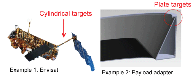
The design of a gripper is usually dictated by the shape and dimensions of the target object. In the case of space objects, it is possible to identify specific parts in the target satellite that are particularly interesting for performing capture operations. Two examples are reported in Figure 1. In the left picture, the well-known case of the ESA's ENVISAT [10] satellite is depicted. One of structures that have been consideredas a possible graspinglocation is the boom connecting the large solar panel to the main bus. The object has no particular structural strength, yet it could be useful to grab and hold it in order to prevent undesired solar panel vibrations during the operations. In the right picture of Figure 1, the more general case of a payload adapter of a launcher's last stage is depicted. This component, holding the satellite to the rocket body, is present in all the launchers' arrangement, it is designed to resist to large loads intrinsic to the launch, and, pending specific constraints, could be often selected as one of the grasping points.
This short overview has the scope to highlight that even if no standardization is usually applied to space products, the class of objects to be grasped is not really wide. In this work, cylindrical and plate (or better, prismatic) targets are considered, as in Figure 1.
With respect to multi-purpose terrestrial applications, therefore, the degree of adaptivity of the space end effector is rather limited. More often, a greater attention is focused on the requirements of lightness and above all of reliability of the mechatronic system. In this sense, a reduced number of degrees of actuation also reduce the relevant potential failures. These considerations have led to the selection of a peculiar design for the end effector, which must be able to grasp both cylindrical and prismatic targets firmly with a minimum number of actuators, specifically only one.
Underactuated three fingers end effector
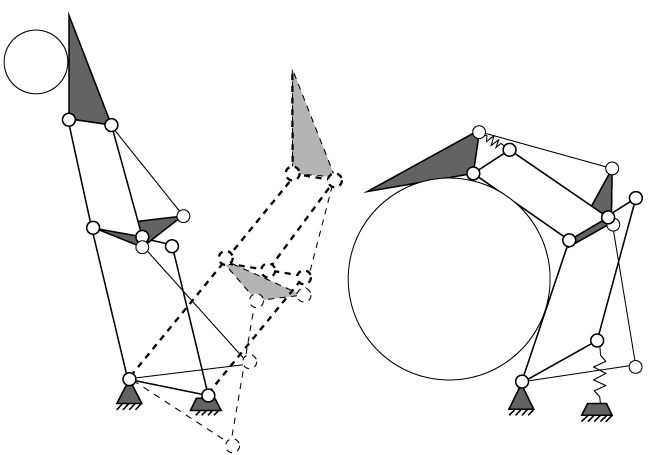
The main source of inspiration for the design of the end effector is the work performed for the realization of the SARAH (Self Adaptive Robotic Auxiliary Hand) robot [9]. In detail, the single finger (as depicted in Figure 2) is made of three phalanges, named proximal, intermediate and distal as in the human hand, which are connected by revolute joints and torsional springs. A system of cranks and rods on the back of the phalanges enables the coordinated motion of the finger. The total number of links is nine (three phalanges, three rod-crank mechanisms), with a resulting number of degrees of freedom equal to three. The goal of the torsional springs is to increase the stiffness of the system, which must at least with stands its own weight without collapsing.
If the length of the phalanges, of the rods and of the cranks, and the position of the revolute joints are correctly selected, a single vertical force applied to the proximal phalanx allows for different movements of the finger, according to the different obstacles (or targets) encountered in during the motion. In this way, the finger is able to adapt both to prismatic and cylindrical objects, as required in the space case, as in Figure 2.
As suggested in [9], the use of three fingers seems a good compromise for grasping since it is the minimum number of fingers required to accomplish stable grasps. Two solutions are proposed in [9] to assemble a complete end effector: first a twelve DOF (Degree-Of-Freedom) and six-degree-of-actuation (DOA) robotic grasping hand is proposed; then the design is modified in order to reduce the DOA. As a result a Ten DOF and two DOA robotic grasping hand is proposed and realized. The ten DOF take the three DOF per each fingers into account, plus the rotation of the fingers about the vertical axis (introduced at the scope of moving the fingers toward a common center, useful just for spherical targets).
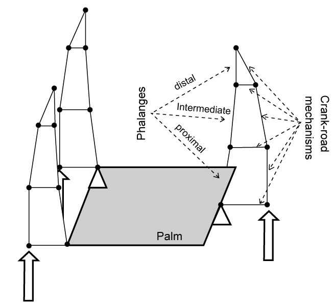
In our case the task of manipulating spherical objects, having in minded the requirements of space missions explained in Section 2, can be considered unnecessary. The DOF (and relevant DOA) for the rotation of the fingers about the vertical axis is therefore removed.As a result, the selected concept for the space end effector is a nine DOF and one DOA hand. The actuation is supplied by a vertical force which is equally applied to the proximal phalanx of all the fingers, as depicted in the concept drawing in Figure 3.
Functional verification via simplified ADAMS model
In order to select the length of the links and the position of the revolute joints, a simple model of the finger has been developed using the MSC Adams software. This phase of the design is preliminary to the actual virtual prototyping. The difference between the preliminary model and the virtual prototype is that in the first functional verification the parts of the multibody model are modeled with primitive shapes (cylinders, boxes, spheres) and not with their actual mechanical design. It should be noted that the simulations have been run both with the presence of the gravitational force and without it. In fact, the experiments are subject to gravity, and this leads to the need of designing some components (in particular the torsional springs) so that the fingers do not collapse under their own weight. This problem would not be present under zero-g conditions. However, a grasp in space could be complicated by the fact that the platforms are not constrained, and an impact of the end effector on the surface of the target could bring the two bodies to get separated. In the mission scenario that is under consideration, however, the mass and inertia of the spacecraft are so large that this problem is not analyzed in this work.
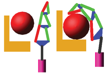
The preliminary model allows verifying the qualitative behavior of the finger. By parametrizing the most critical quantities, such as the phalanges' length and the revolute joints position, it is possible to perform a large number of simulations in a limited time, and even to set up an optimization process. Thanks to this iterative process, the concept design is refined, passing from a functional failure (an example is depicted in Figure 4) to a successful grasp (Figure 5). The evaluation of the concept of "failure" and "success" at this point of the design is still a qualitative one. For example, the wrong position and dimensions of the links in Figure 4 is the cause of the unwanted back folding of the finger when the actuation force is applied by the vertical piston (purple cylinder in the figure) to the finger. Indeed, the target (red circle in the figure) cannot be grasped. By modifying the configuration (in particular the position of the revolute joints), a completely different dynamic behavior is obtained (shown in Figure 5), with the desired bending of the finger towards the target, that is effectively grasped.
Similar tests have been performed for a variety of target bodies, with different shapes and dimensions; the configuration selected for the actual mechanical development must not be considered as optimal for all possible objects, since it was not the aim of the study. The main driver for the selection was a reasonable trade-off for an effective (even if sub-optimal) grasp both for the cylindrical and prismatic cases analyzed. At the end of this first simulation campaign, also quantitative evaluations of the effectiveness of the grasp have been performed. As shown later for the virtual prototype, the contact forces between the target and different parts of the hand (the palm, the phalanges) have been taken as the main index of the success of the maneuver. The result is a set of fingers dimensions and joints positions that are used to design the CAD model that is necessary for the development of the virtual prototype.
Virtual prototyping
For grasping tasks, contact forces play an important role; their actual value depends on the contact surfaces, hence the detailed shape of the bodies can change the expected performance. This is the reason why, following a successful preliminary design, the final verification is performed by means of a virtual prototype in which all the bodies are imported from a detailed CAD model.
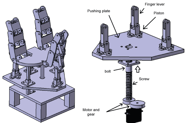
The CAD model is developed considering from the very beginning that additive manufacturing will be used to realize it. The plastic 3D printer device has many advantages with respect to classical instruments (it is faster and cheaper), but also some drawbacks that must be considered during the design: the strength of the plastic material (PLA in our case) is far less than their metal counterpart, and also the precision of the machinery is limited. As a consequence, a minimum thickness of all the parts has been fixed in 4 mm, with a minimum clearance for the moving parts of 1 mm. The mechanical design of the finger is developed taking as a starting point the phalanges' length and joints position selected during the preliminary design; from this data, the distal, intermediate and proximal phalanges are developed, together with the crank-rod mechanism. The resulting CAD model is depicted in the left part of Figure 6.
The solution for applying a vertical force equal to all the fingers is the inclusion of a pushing plate (as in Figure 6-right frame), which is moved by a bolt/screw mechanism. The screw is controlled by means of a 360 degree rotation servo motor, which represents the only actuator of the system.
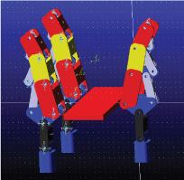
The final version of the virtual prototype is obtained by importing in the multibody dynamic simulator (MSC ADAMS) the CAD model. All the inertia parameters, contact forces, torsional springs and actuation forces are then applied to the imported bodies. The resulting mathematical model is presented in Figure 7. It is made of 34 moving parts, 42 revolute joints, 3 translational joints, 1 fixed joint, with a total of 9 DOF (plus a free target body).
The actuation has not been modeled as caused by the screw/bolt mechanism, like in the real model, since it has been considered a not necessary complication; instead, a vertical pushing force of maximum value equal to 20 N is applied to the piston of each finger (lower blue bodies in Figure 7). The contact forces are included not only between the phalanges and the target, but between all bodies that may interact (such as the crank-rod mechanisms), in order to verify possible mechanical interference. A classic Hertz model of the contact forces has been used [11]. In MSC ADAMS it is implemented as:
Where x is the contact distance, is the zero-clearance distance, is the contact velocity, k is the stiffness coefficient, e is the stiffness exponent, c is the damping coefficient, d is the damping smoothing distance; STEP is a stepwise function of the penetration distance , with zero value at and unitary value at .
For simplicity, the contact parameters have been set as all the bodies were plastic. Of course, this could be true in the experimental case but certainly not in the case of a space scenario. However, auxiliary simulations have shown that the quality of the results does not change if metal-metal contact parameters are used. The only care is that much more stringent numerical integration settings must be set in order to cope with the stiffness of the problem.
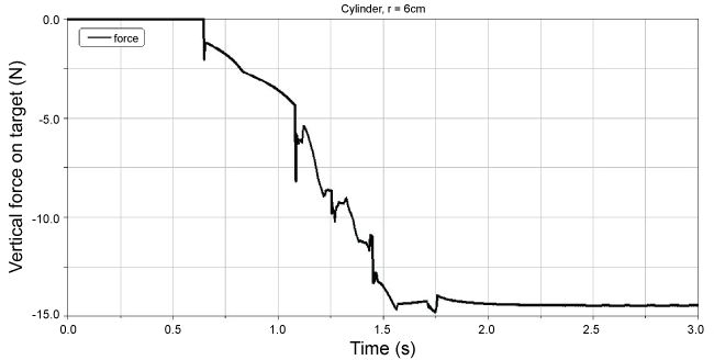
A variety of targets of the two shapes of interest (prismatic and cylindrical) have been tested. In detail, cylinder with base radius ranging from 1.5 cm to 6 cm has been considered, with a successful grasp as shown in Figure 8. The quantitative index for the evaluation of the success of the operation is the resultant of the contact forces applied by the fingers to the target. If the horizontal resultant is null and the vertical resultant is directed downwards, the grasp is achieved. As an example, the case of a cylindrical target of radius 6 cm is reported in Figure 9; as it is possible to see, at steady state the overall force is negative, that, according to the reference frame used, means that the fingers are pushing the target firmly down against the palm of the end effector.
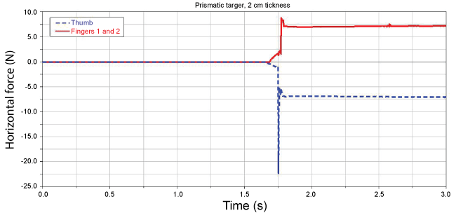
A similar analysis has been performed for the prismatic targets, the width of the targets ranging from 2 mm (actually a plate) to 8 cm. The performance index in this case is mainly the horizontal component applied by the three fingers: the force applied by the thumb-finger (on the right side of the hand in Figure 10) must be balanced by the sum of the force of the other two fingers (on the left side of the hand in Figure 10). An example of the result is reported in Figure 11, showing that for the 2 cm thick target at steady state the grasp has been achieved.
Rapid prototyping
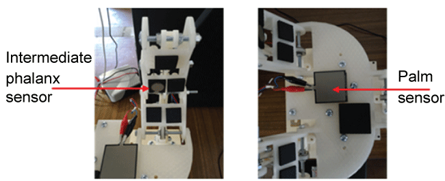
The selected design work flow of the end effector allows for a fast verification of the initial concept thanks to the joined implementation of virtual prototyping and rapid prototyping, which now-a-days can be considered a consolidated technology [14,15]. After the MSC ADAMS model has been used to verify the performance of the end effector in all the cases of interest, it can be directly exported and used for rapid prototyping by means of a 3D printer. A Maker bot Replicator 2X has been used in this project to realize the end effector prototype; PLA material has been used for most of the bodies, including the actuating screw/bolt mechanism. Only the vertical guides, the torsional springs and the axles are metallic. In Figure 12 (left picture) all the printed parts are presented, while in Figure 12 (right picture) the assembled prototype is shown. The base, containing the servo motor and the control board (an ARDUINO 2009) is detached only for a better visualization. The phalanges and the palm are equipped with contact sensors for a quantitative evaluation of the strength of the grasp. In Figure 13 the sensor placed on the intermediate phalanx and on the palm is pictured. The same ARDUINO board dedicated to the motor control also acquires the measurements from the contact sensors, allowing for a feedback control (for example if a maximum-or minimum-grasping force has to be reached).
Experiments
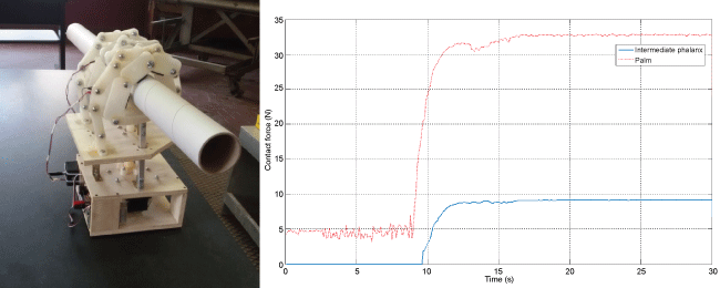
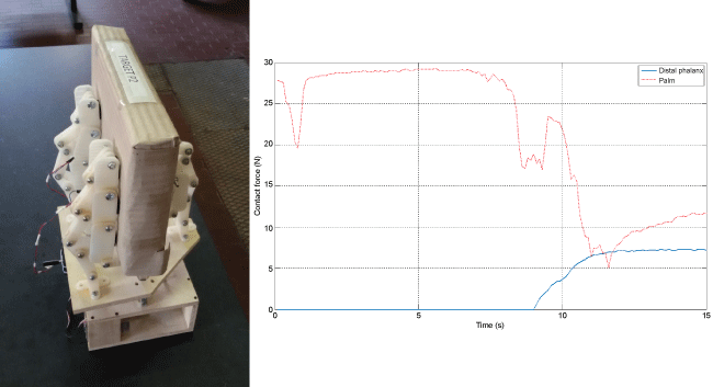
The experiments have been performed in order to confirm the results obtained from the virtual prototype simulations. As it is possible to see in Table 2, the targets' dimensions explored in the experiments exceed the ranges studied in the simulations. Actually, only one failure has been detected, for very small cylinders. Figure 14 and Figure 15 report two examples for the cylindrical and prismatic targets (3 cm radius and 5 cm thickness, respectively). The left pictures of Figure 14 and Figure 15 show that a qualitative conclusion about the end effector capability to grasp different targets can be positively drawn; in fact the fingers automatically bends differently, wrapping around targets of different shapes. In order to quantify the strength of the grab the most significant measurements coming from the contact sensors are reported in the right plots of Figure 14 and Figure 15. For the cylindrical target, the absolute value of the force exerted by the target on the palm and on the intermediate phalanx (the most important in the case of this kind of targets) is reported; considering the three fingers, it is possible to conclude that the target is hold with a force of 30 N (in fact the real motor performance exceeded the simulated one). For the prismatic target, the force exerted by the target on the palm and on the distal phalanx (which plays a most important role in this kind of targets) is reported. It is possible to note that as the movement of the fingers secures the grab, the target in the prismatic case is slightly lifted up, as the decrease in the contact force on the palm indicates.
Finally, tests including targets with a mixed, unpredicted shape have been performed. For example, Figure 16 reports the case of a target built by assembling a P2 target with a C2 target. The picture shows the capability of the fingers to adapt even to the surface of this peculiar combined target, well outside the original designed targets.A short movie showing some of the performed experiments can be found at the Sapienza GN LAB you tube channel, at https://youtu.be/M5Dmi-JN0pI.
Final remarks
The design philosophy for a fast verification of an initial conceptual design has been applied to the case of an end effector for space applications. The main steps involve first a virtual prototyping, i.e. a simulation of a very detailed multibody model, and its realization thanks to the rapid prototyping, i.e. plastic 3D printing. Thanks to this approach, with single design iteration the robotic hand has been realized and tested. The concept of underactuation as a mean for obtaining an adaptive grasp for targets of different shape and dimension has been demonstrated. The physical prototype performed well also for targets different from the baseline ones.
Even though the plastic prototype cannot be considered valid for real orbital applications (because of the hard environmental conditions, such as radiations and extreme temperatures), its successful test for all the targets considered is the proof that an advanced version (not realized via 3D printing) can be considered a reliable solution to the problem of space manipulation and grasping.
Acknowledgements
The authors express their thanks for the support provided by Dr. Daniele Catelani-MSC/Software-in order to fully exploit the features of the MSC ADAMS software used for the simulations.
References
- Andrew Long, Matthew Richards, Daniel E Hastings (2007) On-orbit servicing: A new value proposition for satellite design and operation. Journal of Spacecraft and Rockets 44: 964-976.
- Felicetti Leonard, Gasbarri Paolo, Pisculli Andrea, et al. (2016) Design of robotic manipulators for orbit removal of Spent Launchers stages. Acta Astronautica 119: 118-130.
- Marco Sabatini, Giovanni B Palmerini, Paolo Gasbarri (2016) Analysis and experiments for a system of two spacecraft paired by means of a flexible link. Acta Astronautica 128: 62-71.
- Lovchik CS, Diftler MA (1999) The Robonaut Hand: A Dexterous Robot Hand For Space", Proceedings of the 1999 IEEE International Conference on Robotics & Automation Detroit, Michigan.
- Frederic Didot, Philippe Schoonejanset, Raymond Stott, et al. (2006) Eurobot Underwater Model: Testing the Co-operation between Humans and Robots. In Proceedings of the 9th ESA Workshop on Advanced Space Technology for Robotics and Automation, ASTRA, Noordwijk, The Netherlands, 28-30.
- Thierry Laliberte, Lionel Birglen, Clement M Gosselin (2002) Underactuation in robotic grasping hands. Machine Intelligence and Robotic Control 4: 1-11.
- Montambault S, Gosselin CM (2001) Analysis of Underactuated Mechanical Grippers. Journal of Mechanical Design 123: 367-374.
- Hiroshi Shimojima, Kohtaroh Yamamoto, Kohzoh Kawawita (1987) A Study of Grippers with Multiple Degrees of Mobility. JSME International Journal 30: 515-522.
- Laliberte T, Gosselin CM (1998) Simulation and Design of Underactuated Mechanical Hands. Mechanism and Machine Theory 33: 39-57.
- Daniel Kucharski, Georg Kirchner, Franz Koidl, et al. (2014) Attitude and spin period of space debris envisat measured by satellite laser ranging. IEEE Transactions on Geoscience and Remote Sensing 52: 7651-7657.
- Lankarani HM, Nikravesh PE (2016) A contact force model with hysteresis damping for impact analysis of multibody systems. Journal of Mechanical and Design 112: 369-376.
- Ueno T, Oda M (2009) Robotic hand developed for both space missions on the Inter-national Space Station and commercial applications on the ground. IEEE/RSJ International Conference on Intelligent Robots and Systems, St. Louis, USA, 11-15.
- Rank P (2011) The Deos Automation and Robotic Payload. Proceeding of 11th Symposium on Advanced Space Technologies in Roboticsand Automation, ESA-ASTRA, Noordwijk, The Netherlands.
- Rafiq I Noorani (2005) Rapid Prototyping: Principles and Applications. Wiley.
- CK Chua, KF Leong, CS Lim (2003) Rapid Prototyping: Principles and Applications. (2nd edn), World Scientific Connecting Great Minds.
Corresponding Author
Paolo Gasbarri, Department of Mechanical and Aerospace Engineering, University of Rome La Sapienza, Via Eudossiana, 18, 00184 Rome, Italy, Tel: +390644585324, Fax: +390644585670.
Copyright
© 2017 Sabatini M, et al. This is an open-access article distributed under the terms of the Creative Commons Attribution License, which permits unrestricted use, distribution, and reproduction in any medium, provided the original author and source are credited.

