On Model Checking of a Robotic Mechanism
Abstract
Developing robot control systems can get complex even for small number of functions to be carried by the robot. Finite state machines are representing a frequent approach to model complex systems in a formal way. In this paper we are presenting a methodology for modelling the kinematics of a robotic mechanism represented by a sequence of bodies linked by joints. Each movement is decomposed as a sequence of rotations and translations and a finite state machine modelling the behavior of each of these is built. The general methodology is applied on a case study: A 2 joints manipulator. An Event-B model of each machine is implemented in the Rodin platform, then the models are validated and some LTL properties corresponding to the behavior of the robot are verified using ProB, the associated model checker.
Keywords
Model checking, Robotic mechanism, FSM, Rodin, ProB, 2 joints manipulator
AMS Subject Classification
68Q05; 68Q10; 68Q19; 68Q45; 68Q60
Introduction
In this section some general aspects regarding model checking, Rodin platform, finite states machines and the kinematics of a robotic mechanism with several joints are given.
Model checking, Rodin and ProB
Event-B is a rigorous mathematical modelling language used to implement discrete systems [1]. It was developed by J.R. Abrial as an improvement to the B language. Rodin [2], a platform dedicated to Event-B models is the result of two European Union Projects: RODIN (2004-2007) and DEPLOY (2008-2012) [3]. It is an Eclipse-based IDE that provides effective support for Event-B models including refinement and automatic proving. The platform was extended with plugins such as ProB [4], Camille or iUML-B State-machines.
One of the features of Rodin platform is the possibility to develop the model gradually. The modelling process can start with a simplified version of the system under analysis and more details can be added in a process called refinement. One of the main advantages it that the correctness of each step is proved in order to achieve a reliable system, as the tool assists the development process, by generating proof obligations.
Introduced by Clark and Emerson, model checking is an automatic verification technique of finite-state systems [5]. Since all the possible states of the system are explored in a brute-force manner, the main issue related to this technique is the state explosion problem [6].
The B language is rooted in predicate logic, arithmetic and set theory and it provides support for data structures such as (higher-order) relations, functions and sequences. In addition to the B language, ProB also supports Event-B, CSP-M, TLA+, and Z. ProB is a model checker which accepts B-models and that was also integrated in the Rodin platform as a plugin. It is being used within Siemens, Alstom, Thales and several other companies for data validation of complicated properties for safety critical systems. Animation of Event-B models and verification of properties specified using the LTL or CTL formalisms can be enabled using Pro-B. The provided automated consistency checking can be used to detect various errors in B specifications (deadlocks, invariant violation, etc.). The animation facilities allow: To visualize the state space or to execute a given number of random events.
An Event-B model is a collection of machines and contexts. Contexts describe the static structure of the system: Sets, constants and axioms. Axioms represent properties of sets and constants. Machines contain the dynamic structure of the system: Variables, invariants, and events. Invariants state the properties of variables, and events defines the dynamic of the transition between the states of the system.
Event-B has been successfully applied in some vast areas of investigation from modelling formal ontologies in the engineering area where concepts have been integrated as theories into a specific formal method development process [7], to modelling biological systems such as a basic cell-like P system defined as a hierarchical arrangement of membranes [8], the kernel P system representation of E. coli [9], validating and verifying the requirements and design of a haemodialysis machine [10], up to specifying the dynamic semantics of some real-life industry applications like the formal modelling of a cruise control system [11], of a controller of a water pump for the goal of groundwater conservation [12], modeling a landing gear system of an aircraft [13], a speed control system available in some German cars [14], towards sophisticated air traffic control system using formal methods [15] and applying model transformation and Event-B for specifying an industrial DSL (Domain-Specific Languages) [16].
Moreover, because the development of safety-critical reactive systems is demanding and Event-B allows for a formal software development methodology in which software systems are initially designed in a abstract way and then refined in code, some papers report the work on generating codes for Event-B, applied to very relevant case studies: On the development of an Android application with EventB2Java, on testing an Event-B model of the To-keneer safety-critical system [17] and work towards a translation tool that automatically generates efficient target programming language code (C, C++, Java and C#) from Event-B formal specification related to the analysis of complex problems [18].
Finite state machines
According to [19]: A finite state machine (FSM) is a model of computation consisting of a set of states, a start state, an input alphabet, and a transition function that maps input symbols and current states to a next state.
Several types of finite state machines have been defined starting with the well-known Moore [20] and Mealy [21] machines, and more recently UML state machines [22] and hierarchical featured state machines [23].
Formally, a deterministic finite state machine is a quintuple (Σ, S, s0, Act, F), where:
• Σ is the input alphabet (a finite, non-empty set of symbols).
• S is a finite, non-empty set of states
• s0 ∈ S is the initial state
• Act : S × Σ → S is the state-transition function
• F is the set of final states, a (possibly empty) subset of S
Describing the transition between states, Act is a partial function, i.e. Act (s, x) does not have to be defined for every combination of s ∈ S and x ∈ Σ. The word "deterministic" refers to the fact that from any state s, there is only one transition for any input x such that Act (s, x) is defined.
On the other hand, for a non-deterministic FSM a particular state and an input can lead to more than one state. Since in the next sections we are considering only deterministic FSMs, we will not go into furthermore details regarding the differences between the two types of FSMs.
Finite state machines have been studied intensively due to their simplicity and their computational power, which is equivalent to that of Turing machines.
The kinematics of a robot
One of the most fundamental aspects of robot design, control and simulation, kinematics refers to the motion of bodies in a robotic mechanism without regard to the forces/torques that cause the motion [24].
In general, robotic mechanisms are systems of rigid bodies connected by joints. Therefore, robot kinematics describes aspects like: Position and orientation of the bodies in space, velocity or acceleration. The most common topologies in which bodies can be connected are: Serial chains and fully parallel mechanisms. In a serial chain system, each member is connected to two others, except for the first and last ones that are each connected to only one other member. In a fully parallel mechanism there are two members that are connected together by multiple joints [24].
Related work
The majority of Robot control systems that are developed are Software Engineering based where most of them are following the MDE approach [25]. Finite state machines are good tool to model complex systems that can be formally verified by the different automata tools. The approach taken in developing a FSM model in a tool like Rodin with the Event B language is that it gives a user a methodical way to develop a complex system by using simple construction parts for forming a robust and maintainable system. This is done by breaking down a complex control problem into smaller units which in turn provides a good overview of the overall process. If there are any problems with the structuring or implementation logic it could be easier to diagnose the issue.
A robotic system comprises of at least one robot and the associated devices. Development of such system requires the specifications of the architectures in terms of the structure and the activities to be performed by the system. The structure refers to how the deferent subsystems are composed of and how each of these subsystems is interrelated whereas the activities refer to the actual feature of the subsystem computation and inter-subsystem communications. FSM’s have been used in robot control systems to model complex behaviors and implementation as discussed in [26]. Zielinski, et al. [27] have demonstrated the use of FSM to model the behavior template of a table tennis ball collecting robot. Bolagh and Obdrzalek [28] have also shown the FSM’s can be used in robotic education to teach control systems for different kinds of robots.
An FSM Model of an Arm Robot
Any movement of an arm robot can be decomposed as a sequence of rotations and translations. Therefore, in linear algebra, a complex movement is described as the product of some rotation and some translation matrices. Following this idea, we are defining two categories of FSMs: One corresponding to the rotation with a given angle and another one corresponding to a translation with a given length. For the rotation, the reference point is the origin of the arm and we consider that the arm is able to rotate with 180 degrees clockwise or anti-clockwise. For the translation, the reference point is the end point of the arm which we consider that can be extended up to a maximum length.
For the FSM of a rotation we are considering:
• Σ = {θ}
• S = {INIT, s1 , s2 , STOP, CRASH}
• s0 = INIT
• ACT = {acti|1 ≤ i ≤ 10}
• F = {STOP, CRASH}
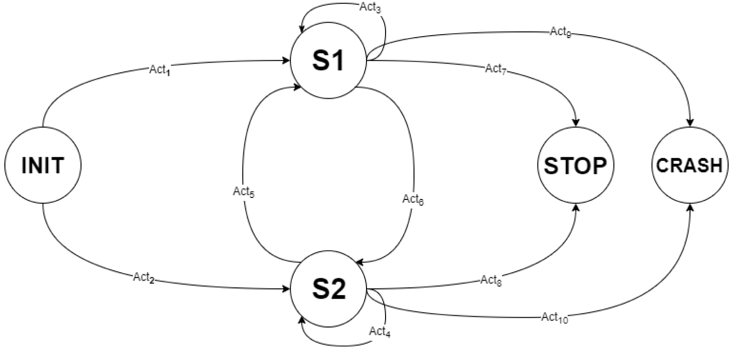
The diagram of the rotation FSM is given in Figure 1.
In the following we are describing the actions of the rotation FSM:
• act1 and act2 are corresponding to the rotation of the arm robot anti-clockwise or clockwise with the angle θ. If 0 < θ < 180, then the movement is anticlockwise, and the state will change to s1 . If -180 < θ < 0, then the movement is clockwise and the state will change to s2
• act3 and act4 are corresponding to any change of the angle θ that are maintaining the states s1 , and respectively s2
• act5 and act6 are corresponding to a change of states between s1 and s2 or vice versa. Any movement that is changing the sign of the value of θ will enable such a transition between states
• act7 and act8 are corresponding to transitions between any of the states s1 or s2 and the state STOP. This happens when the value of θ is -180 or 180
• act9 and act10 are corresponding to transitions between any of the states s1 or s2 and the state CRASH. Such a transition must be avoided in practice as it corresponds to a movement that will break the arm robot.
For the FSM of a translation we are considering:
• Σ = {x}
• S = {INIT, s1 , FINAL}.
• s0 = INIT
• ACT = {acti|1 ≤ i ≤ 4}
• F = {FINAL}
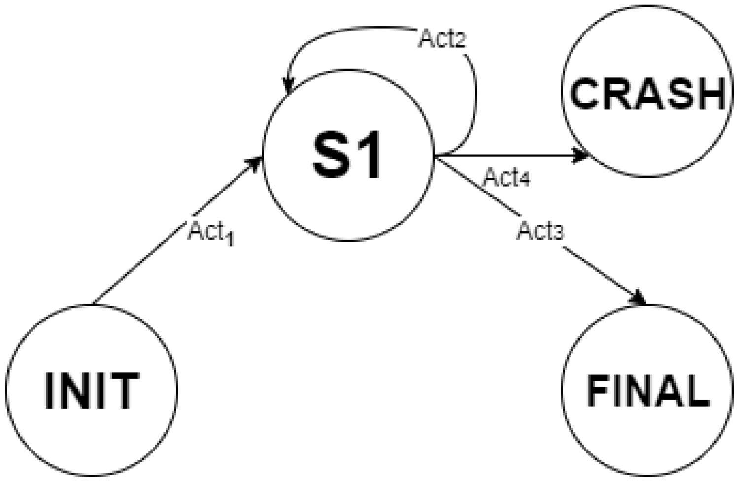
The diagram of the translation FSM is given in Figure 2.
In the following we are describing the actions of the translation FSM:
• act1 is corresponding to an extension of the arm with a value t < MAX. In this case the state of the system will change to s1 .
• act2 is corresponding to any move of the arm such that the maximum length of the arm is not reached. In this case the state is maintained as s1 .
• act3 is corresponding to the reach of the maximum length of the arm and consequently of the FINAL state.
• act4 is corresponding to any "unusual" movement of the arm such that the maximum extension length is exceeded; in this case, state "CRASH" is reached.
Case Study: A Two Joints Manipulator r-θ
In this section an Event-B model corresponding to the kinematics of a two joints manipulator r-θ is investigated. In this case, the kinematics is simple: One joint rotates around the robot’s trunk with an angle θ and one joint slides an arm with length r radially in and out. The model is validated using some of the Rodin facilities and then some properties are verified using ProB.
The Event-B model
The Event-B model is developed following the above methodology, and thus only one rotation FSM and one translation FSM are needed (Figure 3).
The model contains 2 contexts and 2 machines which are corresponding to the static and respectively to the dynamic part of the two FSMs.
The first context (C1) contains the set of states of the rotation FSM: {INIT, s1 , s2 , STOP, CRASH} and {interm} a state that we are considering for the simplicity of the modelling. The corresponding machine (M1) is describing the transition between these states according to the given set of actions.
The context C1 is given below:
CONTEXT
C1
SETS
STATES
CONSTANTS
INIT
s1
s2
STOP
interm
CRASH
AXIOMS
axm1 : partition (STATES,{INIT},{s1 },{s2 },{interm},{STOP},{CRASH})
END
The axiom axm1 shows that any two states are different and their union is the set of states.
The initialisation event for M1 is used to assign initial values for the five variables used in the model. The logics of the assignments is that the system is at the beginning in the initial state (INIT), as a consequence the value of theta is 0, then the arm can rotate with any value (auxTheta) in the interval [1, 359] and the direction of the rotation is given by the sign (+1 is associated with a clockwise and -1 is associated with a anti-clockwise rotation). The variable newTheta is used to update the value of theta, after checking how this will affect the state of the system. The initialisation event is given below:
INITIALISATION
BEGIN
act1 : state = INIT
act2 : theta = 0
act3 : auxTheta :∈ 1.359
act4 : sign :∈ {-1, +1}
act5 : newTheta = 0
END
One of the key events of M1 is move that is enabled if the state has one of the values: INIT, s1 or s2 . In this, the values of two variables are randomly generated: auxθ ∈ -359..359 and sign ∈ {-1, +1} and the state changes to interm. Then, the value of the rotation angle θ is calculated by adding sign × auxθ, and depending of the obtained value, the state of the FSM changes to s1 , s2 , STOP or CRASH. Furthermore, the event move is enabled after each change of states, as soon as none of the states STOP or CRASH is reached.
The event move is given below:
move
WHEN
grd1 : state ∈ {INIT,s1 ,s2 }
grd2 : theta + sign * auxTheta ≥ -180
grd3 : theta + sign * auxTheta ≤ 180
THEN
act1 : auxTheta :∈ 1..359
act2 : sign :∈ {-1, 1}
act3 : state := interm
act4 : newTheta := theta + sign * auxTheta
END
All the other events correspond to transitions between the states of the system according to the updated value of theta. As an example, we give below the event corresponding to the reach of state STOP. Obviously, this event is enabled in the intermediary state when the value of newTheta, the variable standing for the updated value of theta has one of the extremal values -180 or 180
reachStop
WHEN
grd1 : newTheta ∈ {180, 180}
grd2 : state = interm
THEN
act1 : state := STOP
act2 : theta := newTheta
END
The second context (C2) contain the set of states of the translation FSM: {INIT,s1 ,final,CRASH} and interm an intermediate state.
The context C2 is given below:
CONTEXT
C2
SETS
STATES
CONSTANTS
init
interm
final
r
MAX
s1
CRASH
AXIOMS
axm1 : partition(STATES,{init},{interm},{final},{s1 },{CRASH})
axm2 : r = 10
axm3 : MAX = 10
END
The axiom axm1 has a similar meaning to the one in context C1. The other two axioms are used to set the initial length of the arm r and the maximum value of its extension MAX.
In this case, the key event is translation which is enabled in any of the states INIT and s1 , and in which the values of two variables are randomly generated: sign ∈ {-1; +1} and t ∈ 1..MAX. The event is given below:
translation
WHEN
grd1 : state ∈ {init,s1 }
THEN
act1 : t :∈ 1..MAX
act2 : state := interm
act3 : sign :∈ {-1; 1}
END
Then the value of the variable corresponding to the length of the arm is calculated by adding sign × t and as soon as the maximum length is not reached, s1 is enabled. When the maximum length of the arm is reached, the state is updated to FINAL, and state CRASH is associated with the unlikely behavior that the length of the arm could exceed r + MAX or could be less than r.
Model validation: Model checking, proof obligations and properties verification
This section is dedicated to the validation of the model by using various Rodin features.
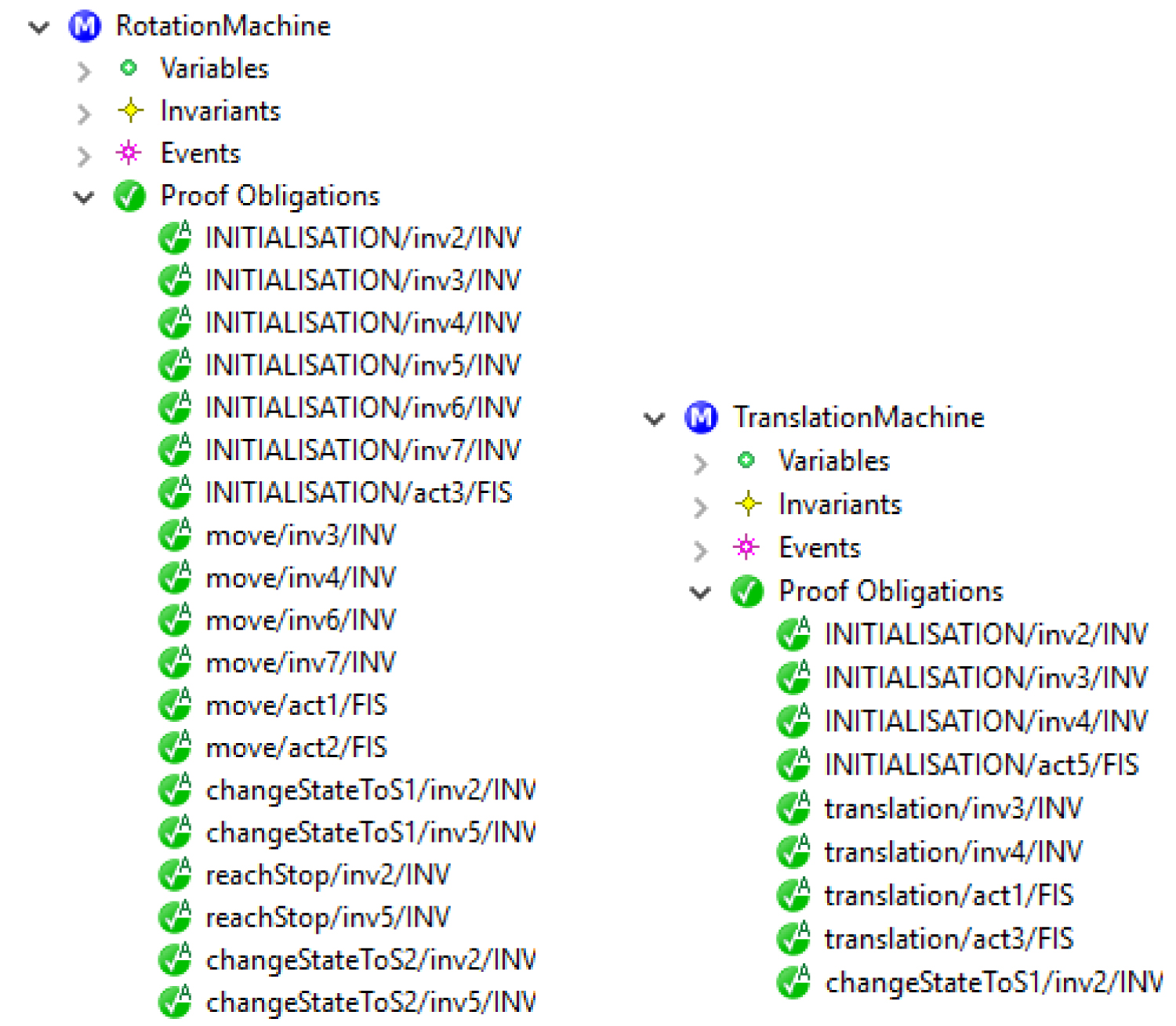
As can be seen in Figure 4 all proof obligations (POs) have been automatically generated and validated by the system.
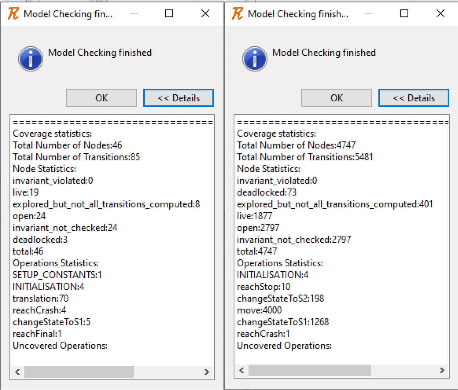
Furthermore, running the model checking on both machines, it can be seen that all states have been visited and there is no invariant violation (see Figure 5).
All these ensure a primary validation of the model which can be enhanced with verifying LTL properties that are describing the behavior of the manipulator.
Thus, the model is verified against some properties and the results are given in Table 1. Although most of the verified properties are simple, we consider them to be significant in terms of model correctness and functionality.
Advantages and limitations
The main advantages of using Event-B and the Rodin platform are the simplicity of modelling, the automatic validation of the models and the model checking and animation facilities. The robustness of an Event-B model is rooted in the rigor of the mathematical language behind and in the correctness of the model that is ensured in each stage of the modelling process through various automatic mechanisms. Moreover, the refinement technique allow users to develop the models gradually, and thus to include in the current model only those features essential for the purpose of that stage. On the other hand, we mention as the main limitation the numerical data types that are restricted to subsets of integers.
Conclusions and Future Work
Robotics is one of the main research areas nowadays, and several methodologies have been developed, however using mathematical modelling combined with model checking is a new approach for simulating and testing the behavior of a robot.
Although our methodology has some restrictions arising from the limitations of the Event-B language and of the Rodin platform, we consider that our paper represents a significant step in this direction.
Our future work will concentrate on applying a similar methodology for other types of robotic mechanisms. We are considering as a first extension to develop a hierarchical state machine based model of a redundant robotic mechanism, and to implement the corresponding Event-B model into the Rodin platform. Moreover, we also plan to investigate other modelling languages and platforms that could help to overcome some of the current limitations.
References
- Abrial JR (2007) A system development process with Event-B and the rodin platform. In: Butler M, Hinchey MG, Larrondo-Petrie MM, Formal Methods and Software Engineering. (edn), ICFEM 2007, Lecture Notes in Computer Science, Springer, Berlin, Heidelberg 4789.
- Event-B website.
- DEPLOY website.
- ProB website.
- Edmund M Clarke, Orna Grumberg, Doron A Peled (1999) Model checking. The MIT Press.
- Edmund M Clarke, William Klieber, Milos N, et al. (2011) Model checking and the state explosion problem. LNCS series 7682.
- Yamine Ait Ameur, Idir Ait Sadoune, Kahina Hacid, et al. (2018) Formal modelling of ontologies: An Event-B based approach using the rodin platform. Electronic Proceedings in Theoretical Computer Science 271: 24-33.
- F Ipate, A Turcanu (2012) Modeling, verification and testing of P Systems using rodin and ProB. Proceedings of CMC12: 12 th International Conference of Membrane Computing.
- A Turcanu, L Mierla, F Ipate, et al. (2014) Modelling and analysis of coli respiratory chain. Applications of Membrane Computing in Systems and Synthetic Biology 7: 247-266.
- Hoang Thai Son, Snook Colin, Asieh Salehi, et al. (2018) Validating and verifying the requirements and design of a haemodialysis machine using the rodin toolset. Science of Computer Programming 158: 122-147.
- SN Predut, F Ipate, M Gheorghe, et al. (2018) Formal modelling of cruise control system using Event-B and rodin platform. IEEE 20th International Conference on High Performance Computing and Communications; IEEE 16th International Conference on Smart City; IEEE 4th International Conference on Data Science and Systems(HPCC/SmartCity/DSS), 1541-1546.
- Rahul Karmakar, Bidyut Biman Sarkar, Nabendu Chaki (2020) Event-B based formal modeling of a controller: A case study. EasyChair.
- A Mammar, R Laleau (2015) Modeling a landing gear system in Event-B. International Journal on Software Tools for Technology Transfer 19: 167-186.
- A Mammar, M Frappier (2020) Modeling of a speed control system using Event-B. International Conference on Rigorous State-Based Methods 12071: 367-381.
- Jarrar Abdessamad, Balouki Youssef (2018) Towards sophisticated air traffic control system using formal methods, Modelling and Simulation in Engineering.
- U Tikhonova, M Manders, M Brand, et al. (2013) Applying model transformation and Event-B for specifying an industrial DSL. CEUR Workshop Proceedings, 41-50.
- Víctor Rivera, Néstor Cataño, Tim Wahls, et al. (2015) Code generation for Event-B. International Journal on Software Tools for Technology Transfer 19: 31-52.
- Mery Dominique, Singh Neeraj (2011) Automatic code generation from event-B models, ACM International Conference Proceeding Series.
- Paul E Black (2016) Dictionary of algorithms and data structures. NIST.
- Moore Edward F (1956) Gedanken-experiments on sequential machines. In: CE Shannon, J McCarthy, Automata Studies. (edn), Annals of Mathematical Studies, Princeton University Press.
- Mealy George H (1955) A method for synthesizing sequential circuits. The Bell System Technical Journal 34: 1045-1079.
- Douglass Bruce Powel (1999) Doing hard time: Developing real-time systems with UML, objects, frameworks, and patterns, Addison Wesley, 749.
- Vanderson HF, Adenilso S, Reza MM (2019) Hierachical featured state machines. Science of Computer Programming 171: 67-88.
- Waldron K, Schmiedeler J (2008) Kinematics. Springer Handbook of Robotics. Springer, Berlin, Heidelberg.
- Brugali D, Cisternino G, Colombo D, et al. (2007) Trends in robotic software frameworks. Software Engineering for Experimental Robotics, 259-266.
- Figat Maksym, Cezary Zielinski, Rene Hexel (2017) FSM based specification of robot control system activities. 2017 11th International Workshop on Robot Motion and Control (RoMoCo).
- C Zielinski, M Figat, R Hexel (2018) Robotic systems implementation based on FSMs, Conference on Automation 742: 441-452.
- Balogh Richard, David Obdrzalek (2018) Using finite state machines in introductory robotics. International Conference on Robotics and Education RiE 2017 829: 85-91.
Corresponding Author
Adrian Turcanu, School of Mathematics and Computer Science, Heriot-Watt University Dubai Campus, Dubai, United Arab Emirates
Copyright
© 2020 Turcanu A, et al. This is an open-access article distributed under the terms of the Creative Commons Attribution License, which permits unrestricted use, distribution, and reproduction in any medium, provided the original author and source are credited.