A Robotic Transportation System via Hybrid Jump-Gliding Locomotion
Abstract
In this paper, various methods of bio-inspired locomotion are investigated with the objective of designing a robotic system to transport a payload via the convention of repeatable jump gliding. The authors provide the mission objective of transporting a payload over a stepped incline, and propose a winged bipedal robot parameterized under the bounding requisites that such a system be capable of exploiting the joint locomotive implications of jumping and gliding for a series of controlled flights and subsequent landings. Of particular interest is the consideration of the initial energy investment 'jump' required to become airborne. Characterizing the lift required to maintain the system airborne, and wing-articulation to alter flight-control moments (and consequent attitude control) provide an explicit investigation into aviary locomotion. Equations of motion are described and utilized in a simulation to validate the system configuration. Environmental factors such as wind were considered for an increased fidelity in the bio-inspired nature of the robot. Simulation implementation is conducted using Matlab and Python, with Autodesk Fusion 360 for visual modeling, Simulation Design Environment for finite elemental meshing, and CFD Motion for computing the fluid dynamics.
Keywords
Bio-Inspired locomotion, Biomimetics, Aerodynamics, Jump-Gliding, Micro aerial vehicles
Introduction
Literature review
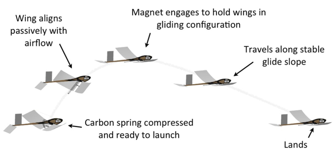
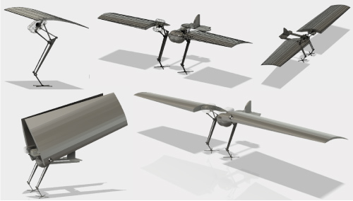
Jumpgliders have been conceptualized in various implementation. Inspiration has been drawn from everything from flying fish [1], to locusts [2], and birds [3,4] (Figure 1). Motivations for gliding after a jump primarily benefit increased distance traveled for a given energy input. This range of travel can increase the speed at which a bipedal system traverses difficult terrain [3]. As this paper's proposed robot is traversing an incline, the primary benefit of a winged-bipedal is to reduce the amount of load the legs must overcome to land without plastic deformation and reduction of mission-limiting fatigue.
Of particular interest on the jumping from is the design presented by Kovac, at al. [5], wherein a mechanical cam is used to slowly build potential energy before releasing it. In the context of a robot that both glides and jumps, the cam can be rotated during flight, allowing rapid takeoff after the robot has landed.
Experimental objective and system configuration
To bound a design environment for the transportation of a payload over an incline, the authors defined a common geometry: A stepped-staircase. The height of the steps on the staircase was taken at 80 cm, with steps every Significant inspiration was drawn from Salto1P [6], wherein a 98.1 g jumping robot is presented that achieve 1.25 m vertical jumping height. Our leg design is very similar, with some parameter tweaking to support the gliding portion of the trajectory. Our expectations for the jump height and launch speed are heavily drawn from their results. A key difference is the departure angle: The model presented here uses a carefully determined launch angle, as the horizontal velocity is a chief concern to prevent stall, while simultaneously ensuring adequate height to allow for multi-step traversal of the staircase. Salto-1P [6] also uses mini propeller blades and an articulated tail for attitude control midair, which we have replaced with articulating wings.
Locomotion
Bipedal jumping
A jump consists of two sections: The initial acceleration while touching the ground, and the resulting parabolic trajectory. Using our gliding functionality, our jump trajectory will be intercepted at its highest point, and gracefully descend instead of falling. In order to determine the necessary jumping force, we can begin with the end in mind and reverse engineer the process. To climb several steps per jump and leave enough altitude to glide forward, we estimate a minimum jump height to be 80 cm (including a security factor, as recommended by M Kovac, et al. [5]). This jump height is comparable to similar jumping systems, such as Salto-1P [6].
For mathematical purposes we will leave the minimum jump height as yf. Using kinematic equations of motion we find:
Setting y0 = v = 0 and a = g:
This gives us the vertical velocity needed upon launch to achieve any given height. The horizontal velocity requirement is derived from the stall speed of the glider, which will be discussed in the following section.
Using our previously determined 80 cm, we find the vertical launch velocity:
Taking vy = 3.9 m/s and vx = 2.0 m/s, we find the total launch velocity to be 4.38 m/s, with a launch angle from the horizontal of 62.8 degrees.
We can use this to determine the acceleration needed during launch. Another variable is introduced, L, to represent the jumping actuation length. The longer the legs of the robot, the more time is available for acceleration, and thus less acceleration is needed. A lower acceleration is beneficial for multiple reasons, namely the reduced stress on the mechanical system and increased payload safety. Our model has a leg actuation length of 12 cm, which is comparable to Salto-1P [6].
Considering the launch phase, we can use the previously determined v0, which is the launch phase's final velocity, v.
The initial position y0 = 0, and at the end of the jump the robot has increased its altitude by the leg actuation length L. Using the same equation of motion as above:
2gyf = 2a(L) (4)
Solving for a, the acceleration needed throughout the jump, we find:
Using this relationship, we can evaluate robot designs and determine the optimal parameters. Returning back to the original requirements, we set yf = 80 cm and L = 12 cm and solve for the acceleration:
The mechanical system contains two articulating legs for jumping, comparable to the Salto-1P (100 g each), as well as a 56.7 g egg and a 15 g wing. The mass sums to 265 g. We include the kinetic energy of the body on launch:
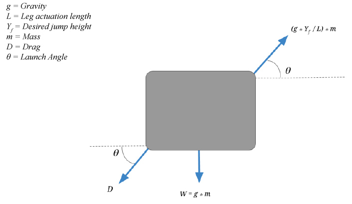
The chief forces of consideration during the jumping phase is the weight of the body itself, the jumping force, and aerodynamic drag (Figure 2).
Gliding
As a process which takes advantage of pressure differentials generated through a finite volume of fluid, gliding conventionally translates potential energy into controlled flight. A form of non-powered aeronautics, gliding relies on geometry specifically tailored to maintain attached flow along the majority of a body (typically referred to as a wing) traveling through a surrounding fluid at a specific range of Reynold's numbers:
Where:
ρ = density of fluid
v = relative velocity of freestream and rigid body
c = chord length of lifting surface
µ = dynamic viscosity of freestream.
Lift generated over the cross section of a surface can be calculated by taking into account for Cl the amount of pressure differential a geometry can conditionally produce), the relative velocity the geometry is traveling through fluid at, the density of the surround fluid, and the surface area of the cross section.
Similarly, we may find the corresponding and penalizing drag force along the same cross section, acting perpendicular to the lift generated above, in steady, level flight:
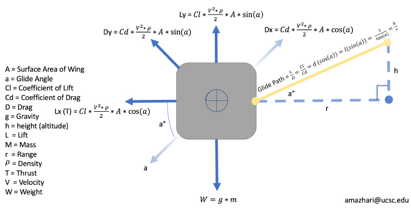
Unpowered thrust generation is typically nonexistent in steady, level flight. The equivalent translational force counteracting the induced drag imposed by lift on a gliding body is provided by the glideslope of the system. The corresponding angle is proportional to the incidence of the wing relative to the surrounding freestream of fluid. The downward angle rotates the lift vector, providing it with an axial component that thrusts the body forward. This angle is accounted for in the corresponding free-body diagram of a lifting body in glide (Figure 3).
Landing
Increasing the Cl by varying the relative angle of attack to generate a geometry and reynold's number-specific Clmax allows conventional airborne objects to land predictably and repeatedly. This angle of attack is typically generated by means of a pitching moment generated by varying geometry. Altering the camber along the lifting body will move the center of pressure, and alter the differential pressure imparted on the surrounding fluid. The resultant forces are increased lift and drag imparted over the body. Birds follow this process to decrease their glideslope for a gentle landing by cambering their wings, shifting their center of gravity, and increasing the angle of attack to near Clmax. The proposed jumpglider in this paper follows a mixture of the same convention, but without the benefits of the favorable weight/drag ratio and elasticity encountered in aviary structures.
Payload
Payload definition
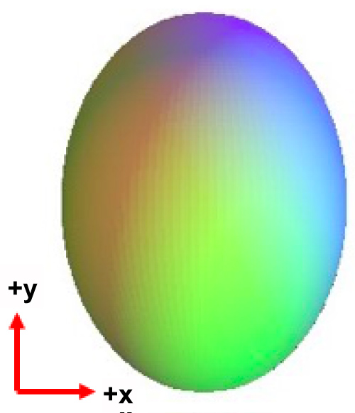
As stated earlier, the mission statement of the bipedal glider parametrized in this paper is to carry a payload up an incline of stairs. Although the required payload is geometrically defined as an ovoid, we will refer to the object as an 'egg' with a centralized, revolving diameter of one inch and a mass of two ounces.
Payload tolerances
The primary performance metric for the bipedal glider robot will be the distance that the system is able to travel without breaking (fracturing) the egg. ADMET, a materials testing manufacturer reports that an ovoid of comparable geometry as able to withstand roughly 50 pounds of force along the y-axis or 90 pounds of force along the x-axis (taking the coordinate system shown in the figure below (Figure 4)). Averaging these component forces (70 lbs) allows for a characterization of the system's allowable loading tolerances with respect to payload impact angle, as seen in the equation below:
Where:
Fa = allowable force, averaged over directional tolerances (70 lbs)
Fi = impact force
α = angle of payload impact from the x-axis.
System Implementation
Parametric simulation
Using Python and Matlab, the jump and glide motions were simulated using various jump heights, launch angles, and glide angles.
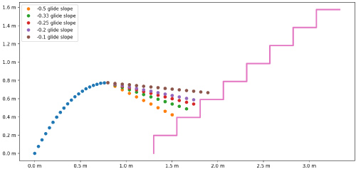
Jumping: As the launch angle (measured from the horizontal) increases, the horizontal velocity decreases, but the maximum height increases. There is a minimum horizontal velocity required to efficiently glide without the craft stalling. For instance, if the launch angle was directly upwards (90° from horizontal), it would not be possible to cleanly transition into glide mode at the top of the jump. While a relatively lower launch angle solves this problem, it introduces another: In order to traverse up a staircase, the jump angle must be significant. Using the parameters determined previously (vy = 3.9 m/s, vx = 2.0 m/s), we plot the resulting trajectory and several glide slopes compared to the staircase in question (Figure 5).
Maximizing the launch velocity is of interest, as it increases both the maximum height, and the horizontal velocity. The limit on launch velocity is primarily the articulating distance of the jumping legs, and the spring constant used to propel the legs. However, there is one limit worth mentioning: The payload (egg) can only sustain a certain amount of acceleration. If the launching operation exceeds this threshold, the egg will be damaged. To deter against such damage, a dampening system was implemented to help cushion the egg during high acceleration periods. Once the jump has reached peak height, the transition to gliding mode occurs, and the parabolic trajectory is interrupted.
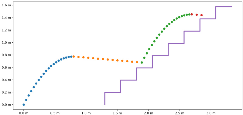
A new variable is now considered, the desired glide slope. The shallower the glide slope, the less altitude is lost, which is desired. As such, the glide slope is set to be the minimum possible while still avoiding stall. This results in a relatively slower flight than if we used a steeper descent, but time is not a parameter of interest in this model. As discussed in the gliding section, the ideal glide angle was found to be -8.9 degrees. A visualization of a multistep jump trajectory using the determined parameters is now presented (Figure 6).
Gliding: To size the surfaces intended to generate lift, the intended scope of the robot was revisited. As the primary mission of this robot is to transport a fairly delicate payload, the bounding characteristics of an otherwise indeterminate series of equations were defined. The lift generated by an aerosurface needed to overcome the gravitational burden of two Salto systems (100 g/each), and a payload (50 g). The second bounding variable was cubic wing loading, as it is a metric that correlates an aircraft's performance characteristics without a relatively high fidelity of volumetric considerations required [7]. A cubic wing loading of roughly seven oz/ft3 was desired to achieve a desirable stalling speed, permitting sustainable flight with a low Reynold's number regime.
Desired Cubic Wing loading:
From the cubic wing loading, a span of 22 inches and chord of eight inches was selected to maintain the reynolds numbers within the scope of a slow-flying, lightly-loaded aircraft capable of generating lift through a gentle (as defined above) landing. At a Clmax of 1.7, the stall velocity can then be defined in m/s by:
Resulting in a Vstall of 4.7 m/s, and a consequent Reynold's number of ≈ 66,000. The following investigation refers to the calculation of the appropriate glidespeed and respective glideslope for various lift-to-drag ratios. The equations and processes are universal amongst aerodynamicists, however the Matlab Aerospace Toolbox [8] was utilized to perform calculations.
Taking W = 0.58 lbf; S = 0.916 ft2, the aspect ratio as AR = 2.66, cofficient of drag at CD0 = 0.04, and an Oswald's efficiency of e = 0.72 provide a true airspeed of:
Converting velocity from f/s to kts gives us 19.79 kts. To confirm the angle at which we will have the highest lift-to-drag ratio, we use:
Providing an idealized glideslope of -8.91 deg. The consequent minimum drag can be calculated as:
At 0.089 lbf. Lift, concurrently provides:
Giving us 0.573 lbf, or 260 g for confirmation of glideslope.
After taking into account for dynamic pressure , we then investigate the coefficients of lift and drag, respectively:
With these figures we can now calculate the encountered drag, consisting of parasitic drag (Dp):
and induced drag (Di):
The sum of which is referred to as total drag (D):
D = Dp + Di (22)
Taking the reconfigured lift coefficient as a factor of weight gives us
CL = 2πα (23)
And finally, we will take L = W.
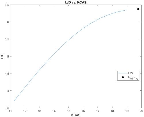
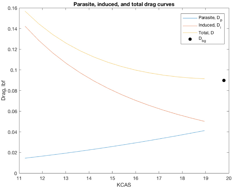
Plotting the data provides us with explicit insight to the optimal glidespeed and glideslope at various considerations calculated above (Figure 7 and Figure 8).
The figures validate that the previously calculated best glidespeed of ≈ 19 kts (or 10 m/s) holds valid under both total drag, and lift-to-drag ratio calculations.
Implementing the aerodynamics
An airfoil capable of generating the required Clmax of 1.7 at the impending α and Reynold's number calculated above was selected [9]. The NACA 4402 was implemented as the baseline and modified for a more-favorable mean aerodynamic camber line. The resulting airfoil is analyzed later in this paper via a computational fluid dynamics simulation. Utilizing Autodesk's Fusion 360 computer drafting software, two Salto [10] jumping robots were integrated symmetrically along the axis bounded by the payload. The egg was implemented into a container located fore of the robot's center-of-gravity (CG) to bias an aerodynamically-desirable forward CG. The wings were originally placed into a typical hangglider configuration, with a single Salto robot underneath. It was quickly determined that a single Salto would not provide sufficient translational momentum to sustainably carry a 50 g payload. The dual-Salto configuration could be implemented with a hang-glider, however the authors decided the benefits associated with independently articulating half-span wings would allow for otherwise unobtainable aerodynamic modes otherwise (such as the wing folding demonstrated in Figure 9).
Finite element analysis
To investigate the fluidic interactions between the proposed model and its environment, a computational fluid dynamic analysis was conducted. The parametric model designed above was resurfaced and simplified in Autodesk's Simultaion Design Environment in preparation of the finite elemental analysis. Meshing was conducted over a three-dimensional grid of roughly 1,000,000 nodes extending +5"/plane occupied by the model's volume. Boundary conditions were placed for standard air temperature and pressure at sea-level (1 ATM).
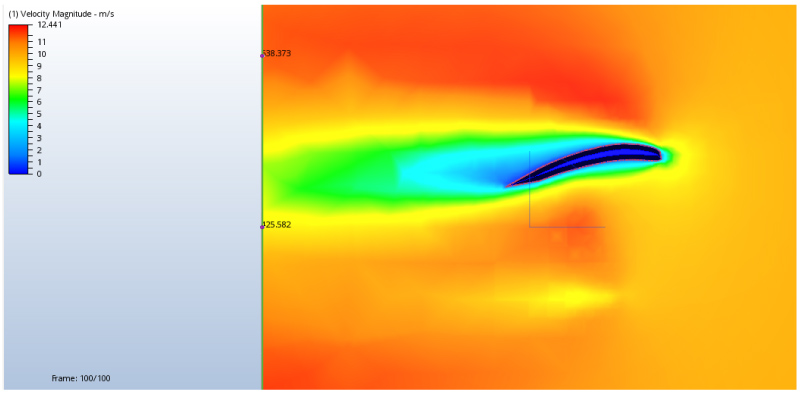
Initial conditions were applied at the desired best-glidespeed of 10 m/s for the inlet, resulting in a steady-state incompressible flow analysis. The outlet was located parallel to the outlet, to reduce the likelihood of simulation divergence. The outlet's initial condition was configured into a low-pressure configuration to influence mass transfer of the high-pressure, upstream. 100 iterations were conducted to average the results of the simulation over the volume. An inquiry to the state of the customized airfoil without interference from the body was conducted and is demonstrated in Figure 9 and Figure 10.
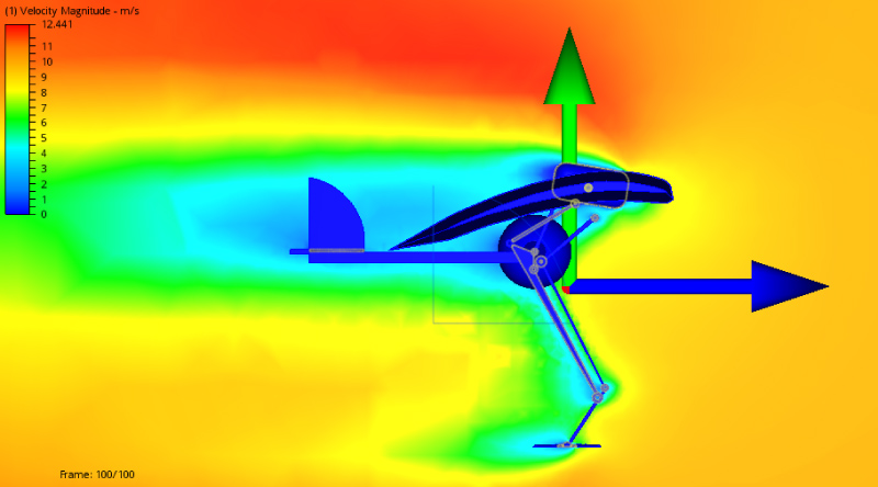
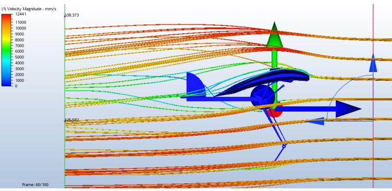
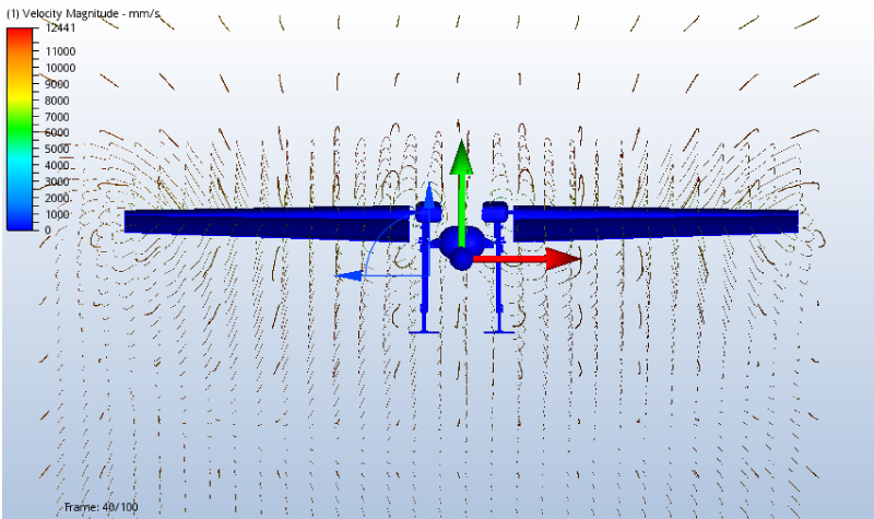
As evident from the flow, a variable pressure gradient along the top and bottom of the airfoil demonstrate relatively healthy flow attached through the aerodynamic center (taken at c/4) for confirmation of lift values calculated above. The average magnitude of velocity over the entire model can be visualized in the Figure 11 and Figure 12 below.
An independent group of 100 fluid markers were implemented at the inlet plane for supplementary insight into the flow behavior.
As evident from Figure 13, the sized empennage requires further-aft placement to account for the interference from the turbulent flow at the aft-third of the wing.
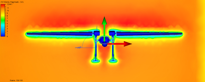
Figure 14 clearly demonstrates that the wing requires tapering to alter the span-wise lift-profile of the wing. The vortex generated at the tip of the wings provides insight to the potential benefits of a winglet (or wing rakes) to reduce the vorticity, and the clearly aggressive lift gradient. These forces result in relatively large drag figures, leading to promising and worthwhile iterations of the wing geometry for an increased lift-to-drag ratio.
Discussions and Future Work
The parametric simulations demonstrate the feasibility of the robot's current configuration for carrying the payload, and consequently completing its mission objective. The FEA provides explicit insight and validation that the system would generate sufficient lift to both maintain the system airborne and reduce the force of landing. The lift generated along glideslope demonstrated that only a single-digit percentage of the allowable force would be traversed into the payload along landing, with respect to the total weight of the robot. Immediate future work leads to iterating the empennage, and potentially resizing it to provide further pitching authority. Further work of interest to the authors is the investigation of differential drag generated extending portions of the aircraft, asymmetrically. As discussed above, tapering the wing for a more sustainable span-wise lift profile and introducing winglets or raked wingtips show promise for improving the robot's aerodynamics. Investigating the benefits of pitching moments from dynamically varying the center of pressure by springing the legs mid-flight for rapid pitching moment oscillations and mode-shifting would allow for curious insight into otherwise under-served research within the field of bio-inspired aircraft. Further work also calls for a follow-on CFD analysis of slow-flight to provide further information regarding the behavior of the robot near aerodynamic stall.
Acknowledgements
The authors would like to thank UC Berkeley's Biomimetic Millisystems Lab and the Salto research team for their inspiration into the development of a uniquely configured jumpgliding robot.
References
- Jiang F, Zhao J, Kota AK, et al. (2017) A miniature water surface jumping robot. IEEE Robotics and Automation 2: 1272-1279.
- Chen D, Chen K, Zhang Z, et al. (2015) Mechanism of locust air posture adjustment. Journal of Bionic Engineering 12: 418-431.
- Desbiens AL, Pope M, Berg F, et al. (2013) Efficient jumpgliding: Theory and design considerations. 2013 IEEE International Conference on Robotics and Automation, 4451-4458.
- Desbiens AL, Pope MT, Christensen DL, et al. (2014) Design principles for efficient, repeated jumpgliding. Bioinspiration & Biomimetics 9: 025009.
- Kovac M, Fuchs M, Guignard A, et al. (2008) A miniature 7g jumping robot. IEEE International Conference on Robotics and Automation, 373-378.
- Haldane DW, Yim JK, Fearing RS (2017) Repetitive extremeacceleration (14-g) spatial jumping with Salto-1P. International Conference on Intelligent Robots and Systems, 3345-3351.
- Simons M, Simons M (1999) Model aircraft aerodynamics. Nexus Special Interests, Hemel Hempstead, UK, 234-241.
- (2015) Aerospace Toolbox. MathWorks.
- Airfoil Tools.
- Haldane DW, Plecnik MM, Yim JK, et al. (2016) Robotic vertical jumping agility via series-elastic power modulation. Science Robotics 1.
Corresponding Author
Mircea Teodorescu, Baskin School of Engineering, University of California, Santa Cruz, USA.
Copyright
© 2020 Mazhari, et al. This is an open-access article distributed under the terms of the Creative Commons Attribution License, which permits unrestricted use, distribution, and reproduction in any medium, provided the original author and source are credited.