Design and Analysis of Drive Mechanism of Piping Robot
Abstract
Piping robots are needed for inner pipe operations in nuclear and oil & gas industries etc. Many pipe inspection robots have been developed. However the payload of these robots is small. To perform heavy duty operations such as grinding, piping robot with large payload must be developed. Furthermore detailed payload analysis which is important for the piping robot design is not available. In this paper, a screw-type drive unit which can handle large payload is developed. Detailed payload analysis is performed to guide the design of the drive unit. To validate the proposed methods, a drive unit was fabricated. Experiments were performed and the results demonstrate that the drive unit can climb inside horizontal pipes as well as vertical pipes with large payload.
Keywords
Piping robot, Drive unit, Payload analysis
Introduction
Piping robots refer to those robots that work inside pipes. In nuclear, oil and gas industries, robots are needed for inner pipe operations [1,2]. Because of limited dimension of pipes, it is difficult to perform operations inside a pipe for human operators. Therefore, piping robots are demanded to carry sensors and equipment to perform specific operations in pipes such as pipe inspection, cleaning, grinding, and other tasks [3-5]. The drive mechanism is very important to drive these robots inside pipes.
There are different driven mechanisms for piping robots such as wheel-type, caterpillar-type, walking-type, helical-type, peristaltic-type and snake-type [6].
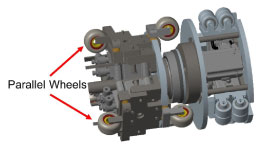
Some parallel-wheel wall-pressed type driving units were developed [7-10], which can be con-trolled with relatively fast speed. Figure 1 shows parallel wheel drive mechanism. For the parallel driven robots, the drive unit could be jammed if there is a dent or an obstacle in the wall of the pipe, Moreover, it is difficult to design a drive unit with large payload using parallel wheel drive mechanisms.
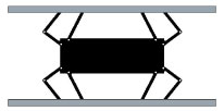
Han, et al. [11] reported a walking drive structure as shown in Figure 2. The driving mechanism can adapt to uneven surfaces. However, it is not suitable for use in a pipe with a certain inclined angle or vertical pipe [12].
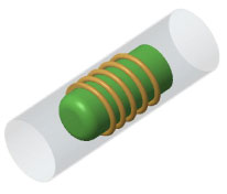
Enner, et al. [13] designed a modular serpentine drive, The drive unit can be used in many complex environments such as sand and water [14], slopes [15], and flat hard terrain [16]. Using friction to move the system forward in inclined or vertical pipes, it is not limited by the diameter of the pipes, and can well cross obstacles at the same time. However, the crawling speed is slow and the robot is not easy to control. Furthermore it's hard for worm-type robot to reach specific location accurately. Kakogawa, et al. [17] proposed a driving method to generate helical motion in pipes. As shown in Figure 3, this kind of drive units has high payload capacity [18-20], thus can be used in tilt and vertical pipes. By adjusting the speed of the motor, the driving speed can be controlled accurately. However, it is very difficult to obtain the optimal helical motion angle and avoid obstacles [21].
Ren, et al. review the screw-type drives in piping robots and present their advantages, but the force analysis is not detailed. Some grinding piping robots have been developed [3,22]; however the design and analysis of drive units are not discussed in detail.
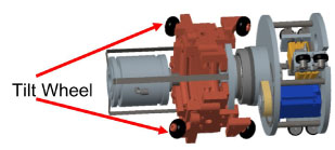
After comparing the advantages and disadvantages of different driving methods, we find that most robots cannot handle large payload. Furthermore the detailed analysis of robot payload is not available. In this paper we propose a robot with tilt wheels to drive it inside a pipe as shown in Figure 4. The robot will move inside a pipe along a helical pattern. Even though there are different robots to climb inside pipes using helical patterns [23,24], the payload of these robots are not analyzed in detail.
In this paper, a drive mechanism of a piping robot with large payload is designed and fabricated. The drive mechanism can adapt to pipe diameters in a certain range. More importantly the force analysis between the tilt wheel of the robot and the inner wall of the pipe is discussed in detail. Experiments were performed to validate the proposed method and designed drive mechanism.
Proposed Solution
This section presents the design of the drive mechanism of a piping robot, analysis of robot payload and drive motor selection.
Design of drive unit
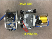
A drive unit with tilt wheels is designed to drive the robot in a pipe. The drive unit is shown in Figure 5.
There are several major parts in the drive unit: Motor, pneumatic cylinders, tilt wheels and linkages. A motor is used to rotate the drive unit. Each tilt wheel is connected to a pneumatic cylinder which will push the tilt wheel against the pipe wall. The ranges of pneumatic cylinders determine the range of pipe diameters that the robot can climb. The air pressure to the pneumatic cylinder generates the press force. The friction force between the wheels and pipe wall prevents the robot from falling. The motor torque is applied to rotate the wheels to drive the robot to move forward or backward.
Analysis of payload
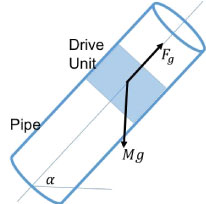
The piping robot is developed to perform grinding operation, which requires large payload. In order to make turns inside bent pipes, a piping robot typically has several units such as drive unit, control unit and operation units, which are connected by flexible links. Figure 6 shows a drive unit inside a pipe.
It is reasonable to simplify the robot using one block for analysis as shown in Figure 6. As we can see, the drive unit must overcome the force generated by gravity and friction. The following equation can be developed based on the force diagram shown in Figure 6.
where Fg is the force generated by the drive unit; M is the total mass of the robot; µ1 is the friction coefficient between the wall and wheel for sliding; α is the tilt angle of the pipe.
Because the pipe inner surface is typically very smooth and the wheel surfaces are also smooth, the friction coefficient is small. Hence we can reasonably simplify Eq. (1):
This means that the largest force required to hold the robot in position is when the pipe is vertical. Hence we will only consider the condition when a pipe is vertical. Considering the safety issues, the drive force generated by the drive unit must be much larger than the weight of the robot.
Analysis of drive force
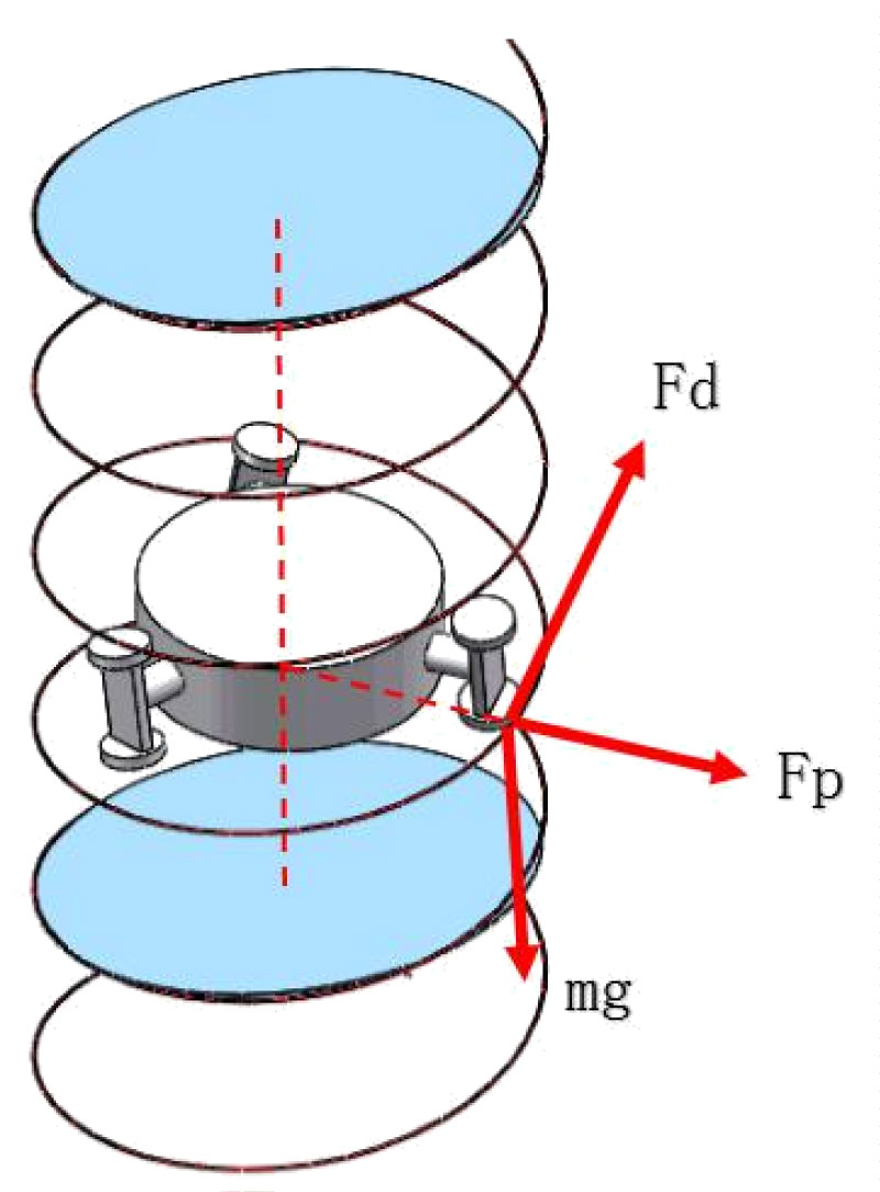
Figure 7 shows the force diagram for a tilt wheel of a drive unit. The wheel could rotate at a certain angular speed and slide down along the pipe wall if the friction force cannot hold the robot. There are two friction forces generated along two perpendicular directions: horizontal and vertical (gravitational). The horizontal friction force is caused by rotating the wheel and vertical friction force is generated along the gravity direction to prevent the wheel from falling. Assume their coefficients are µr and µg respectively. As we know, µg >> µr.
When a tilt wheel rotates and the robot moving upwards in a vertical pipe, the following equations can be obtained:
where Fd is the drive force generated by the drive motor; Fp is the force generated by pneumatic cylinders; γ is the tilt angle of the wheels. m is a mass (for a robot with n tilt wheels, m = M=n).
From the above equation, we have:
Motor selection
Once the drive force Fd is determined, the motor torque can be computed. From Figure 7, we can see that:
where is the required torque to drive the robot; R is the pipe radius. Using Eq. (4), we have:
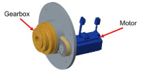
Figure 8 shows part of the drive unit including motor and gearbox. As shown in Figure 8, a gearbox is used to reduce the rotational speed. The motor torque can be computed:
where is the motor torque and β is the gear ratio.
Because µg >> µr, Eq. (7) can be simplified:
In motor selection, we choose the motor torque much larger than the torque calculated using Eq. (8) considering safety requirements.
Experimental Validation
From Eq. (8), we can see that the wheel tilt angle, gear ratio and number of tilt wheels must be determined.
Wheel tilt angle
When the title angle of driving wheel is too small, it will affect the climbing speed of the piping robot. When the title angle of driving wheel is too large, the load capacity of the piping robot will decrease, and the risk of robot falling will increase. Finally, we set the tilt angle of driving wheel to be 15o.
Drive unit
Figure 9 shows the manufactured drive unit. The driving mechanism is mainly composed of drive motor, gear box, tilt wheel, pneumatic cylinder and supporting mechanism. There are three tilt wheels to drive the robot. Each wheel is connected to a pneumatic cylinder. During operation, the pneumatic cylinders extend the tilt wheels to press against the pipe wall. Friction force is then generated to hold the robot from falling. The driving mechanism also moves the robot forward. The moving speed of the robot can be changed by adjusting the tilt angle of the wheels. We used a gearbox with a gear ratio 10.
Design parameters
The robot is implemented to climb a pipe with diameter 260 mm. From the above description, we have the following parameters:
The weight of the robot is about 69 Kg. Considering safety issues, Mg is set to be 80 Kg, Using Eq. (8), the motor torque can be calculated:
Hence a MQMF011L1 motor with maximum torque 1.11 Nm is selected.
Fabricated piping robot
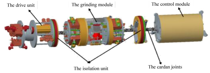
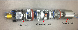
Based on the design requirements, a piping robot is fabricated as shown in Figure 10. The total weight of the robot is about 69 Kg. There are three units: drive unit, operation unit and control unit. There are flexible connections between units such that the robot can climb inside bent pipes. The diameter of the robot is about 260 mm. With the pneumatic cylinders installed in the drive unit, the robot can climb pipes with diameter range from 260 mm to 320 mm.
Experimental results
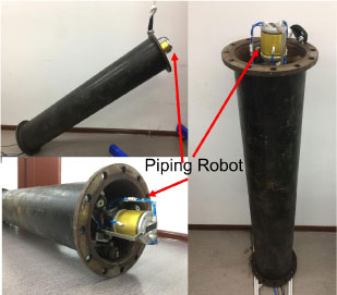
The developed robot was tested using a pipe with different tilt angles: 0o, 45o and 90o. Figure 11 show the results. The drive unit can drive the piping robot to finish grinding task in a vertical pipe.
Conclusion
A screw-type drive unit has been designed, fabricated and tested. The drive force is analyzed in detail. Based on the payload requirement, a motor was selected to drive the robot. The experimental results show that the drive unit can be operated in pipes with different tilt angles. The large payload of the drive unit enables the piping robot to carry more functional units and perform various operations.
References
- P Yu (2017) Research and application of piping inside grinding robots in nuclear power plant. Energy Procedia 127: 54-59.
- Q Zhang, H Chen, J Ye (2009) Tracking and localization system for pipeline robot. Mechatronics 19: 76-84.
- X Du, D Chen, W Tan, et al. (2016) A novel robotic system for inner wall derusting and grinding of pressure pipelines. Advances in Computer Science Research.
- M Tavakoli, L Marques (2010) Development of an industrial pipeline inspection robot. Industrial Robot 37: 307-321.
- K Melo, L Paez, C Parra (2012) Indoor and outdoor parametrized gait execution with modular snake robots. International Conference on Robotics and Automation.
- G Mills, A Jackson, R Richardson (2017) Advances in the inspection of unpiggable pipelines. Robotics 6: 11.
- J Moshayedi, S Fard, L Liao, et al. (2019) Design and development of pipe inspection robot meant for resizable pipe lines. International Journal of Robotics and Control 2: 25.
- YS Kwon, B Lee, IC Whang, et al. (2011) A flat pipeline inspection robot with two wheel chains. International Conference on Robotics and Automation.
- Y Shi, P Yu (2014) Research of inner pipe grinding robot applied in grinding subsidiary pipes of three generations of epr nuclear power station. Applied Technology, 1673-6708.
- S Hirose, H Ohno, TM Suyama (1999) Design of in-pipe inspection vehicles for 25, 50, 150 pipes. International Conference on Robotics and Automation 2309-2314.
- Meng Han, Jun Zhou, Xun Chen, et al. (2016) Analysis of in-pipe inspection robot structure design.
- A Madhani, Dubowsky S (1992) Motion planning of mobile multi-limb robotic systems subject to force and friction constrains. Proceedings IEEE Robotics and Automation 134-139.
- F Enner, D Rollinson, H Choset (2013) Motion estimation of snake robots in straight pipes. International Conference on Robotics and Automation.
- C Wright, A Buchan, J Brown, et al. (2012) Design and architecture of the unified modular snake robot. International Conference on Robotics and Automation.
- S Yu, S Ma, B Li, et al. (2011) An amphibious snake-like robot with terrestrial and aquatic gaits. International Conference on Robotics and Automation 2959-2963.
- M Tanaka, F Matsuno (2008) Control of 3-dimensional snake robots by using redundancy. International Conference on Robotics and Automation 1155-1164.
- A Kakogawa, S Ma (2010) Mobility of an in-pipe robot with screw drive mechanism inside curved pipes. IEEE International Conference on Robotics and Biomimetics 13-20.
- H Omori, T Hayakawa, T Nakamura (2008) Locomotion and turning patterns of a peristaltic crawling earthworm robot composed of flexible units. International Conference on Intelligent Robots and Systems 1628-1634.
- T Miyagawa, N Iwatsuki (2007) Locomotion and turning patterns of a peristaltic crawling earthworm robot composed of flexible unitscharacteristics of in-pipe mobile robot with wheel drive mechanism using planetary gears. Proceedings of the international conference on mechatronics and automation 3644-3652.
- J Qiao, J Shang, A Goldenberg (2013) Development of inchworm in-pipe robot based on self-locking mechanism. IEEE/ASME Transactions On Mechatronics 18: 798-805.
- W Neubauer (1994) A spider-like robot that climbs vertically in ducts or pipes. IEEE/RSJ International Conference on Intelligent Robots and Systems 1179-1186.
- Zi-Li Xu, Song Lu, Jun Yang, et al. (2017) A wheel-type in-pipe robot for grinding weld beads 5: 182-190.
- Yujia Li, Qingyou Liu, Yonghua Chen, et al. (2017) Design and analysis of an active helical drive downhole tractor. Chinese Journal of Mechanical Engineering 30: 428-437.
- M Horodinca, I Doroftei, E Mignon, et al. (2002) A simple architecture for in-pipe inspection robots. 2: 198.
Corresponding Author
Heping Chen, Shenzhen Academy of Robotics, Shenzhen, China.
Copyright
© 2019 Zhu D, et al. This is an open-access article distributed under the terms of the Creative Commons Attribution License, which permits unrestricted use, distribution, and reproduction in any medium, provided the original author and source are credited.