Development of a Human-Robot-Collaboration System using the Example of a Riveting Process in Aircraft Assembly
Abstract
Assembly processes in aircraft production are particularly difficult to automate due to a variety of technical challenges including, small batch sizes, large product dimensions, small tolerances, and limited work space. Fully automated systems are expensive and require a large amount of servicing effort during their life time. The developed solution is therefore a semi-automated approach based on Human-Robot-Collaboration (HRC). In the assembly of the aft section of the aircraft the pressure bulkhead must be mounted to the section barrel. During this task, operators must fasten hundreds of rivets. This assembly task is non-ergonomic and current practices require two humans to work cooperatively under burdensome conditions. The alleviation of such work can be achieved through the use of a collaborative scheme between operators and robots.
The developed approach utilizes dynamic task sharing between operator and robot based on ability. The approach is demonstrated through the placement of the robot on a lifting unit inside the aircraft section while the operator performs their tasks outside on top of the pressure bulkhead. Using dynamic task sharing, smart devices, and an intuitive control system a synchronization of human and robot is realized as tasks are completed collaboratively. An overall process recording is used to enhance the quality of the assembly sequences. The results are part of the European Union's Horizon 2020 research and innovation program and present hybrid automation shown in the HRC riveting process.
Keywords
Automated large-scale structure assembly, Human-Robot-Collaboration, Assembly process, Riveting
Abbreviations
HRC: Human-Robot-Collaboration; ROS: Robot Operating System; CAD: Computer-Aided Design; TCP: Tool Centre Point
Introduction
High wage costs throughout Europe and the U.S. and the ever-increasing proficiency of manufacturing in low wage countries has led to transfer of production capacities. If manufacturing companies in high wage countries wish to compete, they must adapt and innovate. New production techniques that lower costs and increase efficiency are required to remain competitive and adapt to the changing market conditions.
The aircraft production industry is an ideal example of this issue. Today, most assembly processes in aircraft production are performed manually by skilled workers [1]. However, it is becoming more difficult to find these skilled workers due to demographic changes. Automation of these tasks would be the most suitable solution. Nevertheless, a variety of technical risk and challenges make the automation of aircraft assembly quite difficult [2,3]. Factors such as small batch sizes, large product dimensions and limited work space render traditional automation techniques ineffective and expensive. A conventional automation system is unable to handle the variety of needs associated with aircraft assembly. The implementation of a semi-automated process such as Human-Robot-Collaboration (HRC) represents a possible solution to this challenge. HRC scenarios can be found in aircraft assembly such as cooperative sealing processes in large floor grid crossbeams in structural assembly [4]. As collaboration in a hybrid team of human and robot in real-world scenarios is still a challenging research problem, the potential of HRC is demonstrated in the riveting process of the pressure bulkhead to the section barrel 19 in aircraft production assembly.
The results presented in this paper were obtained in the research project "Modularity, Safety, Usability, Efficiency by Human-Robot-Collaboration - FourByThree", funded by the European Commission within the framework of the Horizon 2020 research and innovation program (no 637095). Project objective was the fast and effective set-up of individual HRC robot systems, which are customizable regarding the needs and requirements of the scenario. FourByThree defines the four main system characteristics modularity, safety, usability and efficient for the implementation in Human-Robot-Collaboration fields. The modular approach of the developed components is not only limited to the hardware of the robot, but is also transferred to the implemented software. Apart from the HRC robot arm design, video projectors are used to visualize work spaces and monitor them in combination with camera systems to complete the safety of the whole HRC. With respect to the usability of the robot system, a modular control concept is used, as well as multimodal interaction, like voice and gesture control, and hand guiding or positioning of the robot system using a touch screen. Enhancing the effectiveness is achieved due to the applied HRC in the applications as an easy to maintain and reconfigurable modular robot system.
In order to validate the results of the project, application scenarios such as, manipulation, bolting, welding, and riveting were examined within the FourByThree project. This article is focusing on the collaborative riveting process with human and robot in aircraft production [5].
Current Aircraft Production Process
The aircraft is subdivided into several sections as seen in Figure 1 below. The cockpit is located in the first sections, while sections 13-18 form the fuselage, which represents the passenger area.
The aft section of the aircraft, section 19, closes the passenger area with the pressure bulkhead and the section barrel. In addition, the horizontal and vertical tail planes are mounted to section 19. Within the scope of assembly systems, the section 19 assembly of an Airbus A320 is examined more closely.
As shown and marked red in Figure 1, the pressure bulkhead needs to be mounted to the section barrel 19. This assembly process is currently performed in box assembly by means of a high number of rivets. The overlapping riveting position of the pressure bulkhead with the section barrel is marked orange in Figure 1.
Assembly processes in aircraft production are complex and therefore subject to technological challenges. Technological and organizational challenges include:
- Large production dimensions
- Low tolerances
- High amount of variants
- Several thousands of tasks
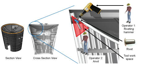
The size of the components interferes with the tight tolerances of manufacturing and assembly processes. Especially when it comes to automated systems for aircraft production is often difficult and expensive to meet the requirements and to identify the different variations which are introduced by a large number of parts and complex joining tasks [6,7]. As a result, many assembly processes in structural assembly, such as the application example of the mounting of the pressure bulkhead to the section barrel, are still not automated. In this assembly process many burdensome and tiring task, such as monotonous overhead work, high noise level due to the riveting hammer and bad ergonomics related to the body postures have been identified within the process analysis. Two operators (see Figure 2) must work manually and cooperatively as the pressure bulkhead is mounted to the barrel. Preparation tasks include the pre-drilling, drilling out, sinking, disassembly, and the application of sealants to approximately 800 riveting points. The first operator kneels on top of the pressure bulkhead, identifies the riveting position, inserts the rivets, and operates the riveting hammer. The second operator needs to be inside the section barrel to position the anvil for the collaborative riveting process. To reach the work space, the operators require racks on the outside and lifting units on the inside of the section. In addition to the troublesome overhead work required by the operator performing the counter-holding task, the exposure to noise and vibrations by the tool is amplified while inside the section barrel. The operator inside the section barrel must therefore remain in an ergonomically unfavourable position, in a confined and noisy workspace, for about 3 to 4 hours of process time. Furthermore, the noise makes communication between the two operators more difficult and only possible by means of knocking signals, which decrease the process efficiency.
Semi-Automated Riveting System using Human-Robot-Collaboration
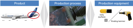
The planning approach used is shown in Figure 3, and the subsequent detailed analysis highlight the importance of understanding the dependencies between these important components of a production process. The resulting requirements obtained from such an analysis were incorporated into the process design and the production equipment selection.
For a variety of reasons, including physically high loads and uncomfortable conditions for the operator situated inside the barrel, it was determined that performing the counter-holder task with an HRC robot would greatly improve the process quality and efficiency.
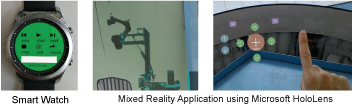
In this application, a robot is placed on a lifting unit inside section 19 to perform the counter holder tasks previously performed by a human. This lifting unit raises the robot into the work space so that it can more easily reach each rivet position. The other operator remains on the outside of section 19 on top of the pressure bulkhead to perform the more complex tasks of inserting the rivets and operating the riveting hammer. To ensure the success of this application, the direct Human-Robot-Collaboration must be intuitive and the operator must have full control over the robot system at all times to ensure process efficiency and the operator's acceptance. Smart devices, such as a smart watch or mixed reality devices are particularly helpful in this application as without them, the operator is unable to see the current position of the robot and interact with the system (see Figure 4). The smart watch gives full control to the operator during the production process by means of an easy to use UI in the operator's wrist. Mixed reality technology improves interaction in the hybrid team of human and robot, due to real-time feedback by visualization of the current pose of the robot system.
The summarized application requirements for a semi-automated system are listed below. These requirements can be met through the selection of an appropriate method, such as those developed in the project TRSE [8]:
1. Large construction dimensions
2. Operation in small work spaces
3. Ergonomic improvements of working conditions
4. Improvements in process quality
5. Traceability of the process
6. Precision and repeatability
7. Natural Human-Robot-Collaboration
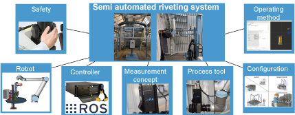
To ensure flexibility of the application is another reason to choose a semi-automated riveting system, as opposed to a fully automated system. The approach, shown in Figure 5, contains seven main components. This semi-automated system calls for specific components to ensure its successful implementation as a Human-Robot-Collaborative riveting process. These specific components include safety devices, a controller, a measurement concept, and process-specific tools. Moreover, the configuration between human and robot needs to be developed. Different configurations exist in a spectrum that ranges from autarkic (local separation but no temporal separation), synchronized (no local separation but temporal separation), cooperation (no local and no temporal separation) to collaboration (no local and no temporal separation, but also working actively together in a task) [9]. Additionally, an easy to use operating method is necessary to combine the components of the semi-automated system and control them intuitively on the shop floor without special programming skills.
Through skill-based task allocation, the human was placed on top of the pressure bulkhead to perform the more complex task of inserting the rivets and operating the riveting hammer in the joining process. The robot was placed inside the barrel to position the anvil, as it is a monotonous and non-ergonomic tasks. This collaborative method thus results in semi automation of the production process which is controlled by a higher level control system. The overlapping of work spaces between the human and the robot system at the same time and the collaborative work on a common task, such as the riveting production process, defines the configuration as Human-Robot-Collaboration. In terms of safety, the removal of barriers leads to increased safety requirements for the system. The robot system and its lifting unit must conform to safety standards such as DIN ISO/TS 15066 to ensure that the operator is not harmed. While market ready robot systems may already fulfil these safety requirements, the lifting unit needs to be outfitted with additional sensors, safety switches or contact-free sensors. Within this scenario a Human-Robot-Collaboration capable robot system as well as a laser scanner for monitoring of the work space guarantees safety. While in the riveting process human and robot are only connected by means of the rivet itself, separation of both participants by the pressure bulkhead avoids collisions with the process execution and increases therefore safety.
The robot controller itself is not sufficient, to properly manage the whole system a higher level control system is needed. The robotic framework Robot Operating System (ROS), which uses a service-oriented architecture, can serve as a base for the development of such a system. ROS provides a collection of tools and libraries and can make robot applications available on a variety of platforms. It can be used for communication between machines in general, robots, sensors, and additional devices. For instance, additional sub-programs have been developed as well as graphical interfaces or the implementation of smart devices. The modular architecture and standardized communication protocols such as ROS or MQTT publish and subscribe methods allow an easily transferred to many robotic platforms without significant effort. For increased efficiency and accuracy in the production process, an adapted measurement concept is necessary to precisely determine the rivet's position. The identification of the workpiece or the riveting pattern is achieved through the use of an optical sensor. Rivet holes can be detected by the sensor during a scan process and the position of the rivet holes with respect to the robot base (x, y, z, α, β, γ) can be determined for the creation of the work model. Additionally, the scanned data can be combined with offline data based on a CAD model to make use of hybrid programming. This makes it possible to put the application into operation quickly and increases the efficiency of the application [10]. In terms of process-specific tools, for this riveting application, the robot is equipped with an anvil for the counter-holder task. The cold forming process, which results from the interaction of the riveting hammer and the anvil, requires a special riveting tool. This tool is needed since the riveting process of a universal rivet requires vibrations that must be minimized to avoid damages to the robot system.
Development of the Riveting Process Tool
In aircraft assembly many different types of rivets have various roles in joining processes, such as pop, hollow, punch or solid rivets. They are additionally distinguishable by head shape, such as countersunk, round, flat, or universal head. In this application, a solid rivet with a universal head is required. The HRC riveting process therefore requires the development of a specific counter-holder tool for the robot system. Requirements for the tool include several aspects. First the tool has to be modular for regular maintenance of important parts such as the anvil mass due to erosion. A safe HRC design can be guaranteed by means of rounded edges and limitations of gap width. Additionally the design has to be adjusted with respect to work space, sensors, such as a force-torque sensor for HRC interaction needs to be integrated, laser line triangulation sensors for process control and referencing, and damping of vibrations caused by the riveting process.
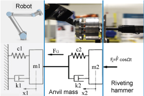
One of the key features of the process tool is the minimization of process forces and vibrations, which are applied by the riveting hammer into the rivet and therefore also into the robot system. Applying the forces, especially the peaks and permanent oscillations, to the robot could result in damage to parts of the system, such as, the joints and gears. To design the parameters of the process tool in such a way that minimizes the process forces, the natural frequency of the robot system and the anvil needs to be identified for the modelling of a dual-mass system. Afterwards optimized parameters for the tool can be calculated and tool prototypes can be built (Figure 6).
Identification of the Natural Frequency of the Robot System and the Anvil
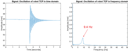
To apply the dual-mass system shown in Figure 6, the parameters of the robot system and the anvil must first be determined. Experimental modal analysis by means of a laser tracker is used to determine the stiffness c1. The robot flange is loaded with 2.5 kg while the wrist is oriented upwards. The displacement of the Tool Centre Point (TCP) is monitored with a laser tracker (Type: API Radian R50) and measured as 0.475 mm in the direction of earth gravity. The stiffness c1 is then calculated as 52 N/mm. The natural frequency of the UR 10 robot must be determined. For this purpose, the robot system is stimulated to vibration and the system response is measured. The stimulation takes place by means of a hammer and dynamically by abrupt stopping of the robot during its planned movement execution. The signal is measured at 100 Hz with respect to the Nyquist rate to avoid measurement errors. The measurement data is displayed as a function of time (Figure 7 left) and therefore a discrete signal. By using a discrete Fourier Transformation the discrete signal can be converted into the frequency range (Figure 7 right).
The corresponding frequency f1 is determined as 9.4 Hz. The effective mass of the robot is then calculated as m1 = c1/(2πf1)2.
The mass of the anvil m2 is known as 2 kg. The anvil's spring stiffness c2 is calculated similarly to that of the robot. Where the anvil is loaded with 3.5 kg and the displacement is monitored. Then, the stiffness c2 is calculated as 11 N/mm.
The system is modelled as a two-mass system that is set up with two linear differential equations of second order (I) and (II).
After inserting the natural vibration values x1 = A1 cos(ωt) and x2 = A2 cos(ωt) in equation (I) and (II), the result can be represented in matrix notation as shown in equation (III).
Assuming that the amplitudes A1 and A2 are only different from zero if the determinant of the two-row coefficient matrix is zero, the quadratic equation is obtained for the frequency. The solution can be described as equations (IV) and (V).
Using equations (IV) and (V), the natural frequencies of the dual-mass system are determined as w1= 8 Hz and w2 = 13 Hz [11].
Harmonic Force Excitation with Frequency-Independent Amplitude
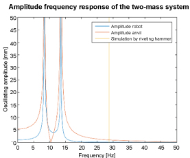
Using the previously calculated values, as well as the two-mass system stimulated by the riveting hammer (see Figure 6 and Figure 7) with a harmonic oscillating amplitude (f = 29 Hz), equations (VI) and (VII) can be determined and plotted as shown in Figure 8. Equations (VI) and (VII) describe a system with harmonic force excitation and a frequency-independent amplitude (Note that angular frequency Ω = 2πf) [11].
The plot in Figure 8 shows the amplitudes of the robot and the anvil, as well as the effacement point. The plot shows two characteristics. Firstly, the areas of resonance for the robot and the anvil are in overlapping areas. Secondly, the effacement point that would cause the anvil to stop swinging is approximately at 10 Hz.
The drawn excitation frequency of the riveting hammer, which lies at 29 Hz, is far from the areas of resonance for the system. The riveting hammer frequency has been determined by means of an acoustic level measurement. The riveting hammer frequency allows the operation of the riveting process in a safe frequency domain that is far from the resonance area of the two-mass system. As a result, damage to the robot manipulator especially into gears during the production process is avoided (Figure 8) [12-15].
Validation and Conclusion
For validation of the developed modular riveting process tool, the demonstrator, which was developed within the framework of the FourByThree project, is used. This replicates the original working space of the section 19 assembly in aircraft production. The previously shown and determined values for the design of the process tool were implemented into a real prototype tool in order to validate the results in practice. To validate the oscillation insulation by the tool, the forces applied to the robot flange during the riveting process are measured. In order to be able to make a statement on how much the spring system reduces the forces and oscillation, a reference measurement was made. The mean value of the forces for a riveting process without a spring is 125 N. In addition, peak forces of up to approximately 195 N occur, which would cause damage to the robot if they were permanently exposed. By using the developed riveting tool with adapted parameters for minimizing forces and oscillations, finally averaged forces of approximately 65 N are measured. In practical comparison, the forces can thus be minimized by about 50%.
As mentioned above, the most important objective, the minimization of the oscillations generated by the riveting hammer has been realized. Consequently, the anvil tool can be mounted to the robot and implemented into the collaborative riveting process. For the riveting process itself, the anvil tool needs to allow basic swings for the forming of the rivet head. This is made possible by designing the spring element based on the previously determined parameters for the two-mass system. Bad oscillations are eliminated, necessary oscillations are accepted. Furthermore, the spring elements is an important part for interaction and control of the robot system. Due to its compressibility two main effects occur. In the process execution, the rivet is inserted by the operator manually. In the next step the rivet is pushed by the operator against the frame using the riveting hammer. While pushing the rivet, the spring is compressed by the operator. During the collaborative riveting process, the anvil tool is eliminating bad oscillation as well as repositioning the swing mass of the tool using the integrated spring element. As a result the robot does not need to perform an online path correction. This allows an easy implementation of the robot, transfers all process relevant parameters to the tool, and finally leads to a Human-Robot-Collaborative riveting process.
Summary
Due to a variety of technical challenges associated with automation, aircraft assembly is mainly characterized by manual processes [11]. Full automation of such an application is challenging and many tasks are still performed manually by trained experts due to their complexity. HRC technology is an effective solution to this challenge and as a way to improve production efficiency, increase production quality, and improve working conditions. The implementation of this robot system alleviates the many burdens placed on the operator inside the section barrel. Setting up a semi-automated system with intuitive control methods, that is easy to install, and has additional assistance systems allows for simple configuration on the shop floor instead of requiring complicated programming. This improves the efficiency of the system and aids in operator acceptance. To ensure a stable process and that no damage comes to the robot system, a special riveting process tool has been developed to decrease the applied forces and oscillations by the riveting hammer. Skill based task sharing, especially in combination with semi-automated systems, offers innovative possibilities for new automation processes, which are particularly helpful for the economic competitiveness of high-wage countries.
References
- Müller R, Geenen A, Vette M (2015) Potentials of Human-Robot-Cooperation in Aircraft Assembly Systems/New possible applications of a human-robot-cooperation in aircraft production by the example of shell structure assembly. SAE Technical Paper.
- Reitter E (2015) Premium Aerotec: Internetadresse. Pressemittelung: Premium AEROTEC eröffnet Werk in Rumänien und setzt Wachstumskurs fort.
- (2015) Global presence - Airbus Group in China.
- Müller R, Vette-Steinkamp M, Geenen A (2018) Sealing process on a large floor grid crossbeam assembly through human-robot-cooperation. International Symposium on Robotics, München.
- www.fourbythree.eu.
- Saadat M, Cretin C (2002) Dimensional variations during Airbus wing assembly. Assembly Automation 22: 270-276.
- Ligget JV (1993) Dimensional variation management handbook, A guide for quality, design and manufacturing engineers. Prentice-Hall, Englewood Cliffs.
- Müller R, Vette M, Geenen A (2017) CIRP - Conference on Assembly Technologies and Systems. Semi-Automated Welding Station.
- Thiemann S (2015) Direct human-robot cooperation in small parts assembly with a SCARA robot. IPA-ILO research and practice, 411.
- Müller R, Vette M, Geenen A (2017) Semi-automated robot welding station for the production of individual parts (TRSE).
- Müller R, Vette M, Quinders S (2012) Handhabung großer Bauteile zur Flugzeugmontage mittels eines Verbunds kinematischer Einheiten unterschiedlicher Struktur. VDI-Bewegungstechnik 2175. Aachen: VDI Verlag.
- www.airbus.com.
- Premium Aerotec GmbH, Augsburg.
- Müller R, Vette M, Geenen A, Masiak T (2017) Improving Working Conditions in Aircraft Productions using Human-Robot-Collaboration in a Collaborative Riveting Process. SAE Technical.
- Masiak T (2018) ZeMA - Zentrum für Mechatronik und Automatisierungstechnik gemeinnützige GmbH, Saarbrücken.
Corresponding Author
Tobias Masiak, M.Eng., Research Assistant, Chair of Assembly Systems, Saarland University, ZeMA gGmbH Gewerbepark Eschberger Weg 46, Geb. 9, 66121 Saarbrücken, Germany.
Copyright
© 2018 Müller R, et al. This is an open-access article distributed under the terms of the Creative Commons Attribution License, which permits unrestricted use, distribution, and reproduction in any medium, provided the original author and source are credited.