Electrostatic Power from Negatively Charged Lunar Regolith
Abstract
Constant bombardment of electrons and protons from the solar wind and energetic plasmas in the terrestrial plasma-sheet has charged the lunar regolith negatively. The dust accumulated on spacesuits, including the vision goggles, by electrostatic charge caused reduced visibility for the astronauts, and was unavoidably transported inside the spacecraft where it caused respiratory irritation. In the lunar vacuum (~10 -12 torr), the maximum charge on the particles remains extremely high because the charge dissipation of the regolith, by random collision frequency of lunar atmospheric molecules, is very low. It is known that the lunar surface is charged with up to several thousand volts, which can hinder surface activities, especially when disturbing large amounts of regolith during base emplacement. To exploit this phenomenon, an electrostatic charge collector with a capacitive storage system was successfully tested to show that the collected charges can be used as a potential power source for a lunar rover or other systems. Through this charge collection process, negatively charged lunar regolith can also be neutralized, and so the adverse effects on astronauts and equipment can be mitigated.
Nomenclature
ESPG: Electrostatic Power Generator; ESP: Electrostatic Power; PVDF: Polyvinylidene Fluoride; SEM: Scanning Electron Microscope
Introduction
The lunar regolith is known to be negatively charged by electrons and protons from the solar wind and by energetic plasmas in the terrestrial plasma-sheet [1]. The charge level of lunar surface can even reach to several thousand volts [2]. During the Apollo 17 lunar mission, charged lunar dust was a major hindrance, as it was attracted to the astronauts' spacesuits, equipment, and the lunar buggies [3-5]. Dust that accumulated on the spacesuits, including the vision goggles, also caused reduced visibility for the astronauts, and was unavoidably transported inside the spacecraft where it caused respiratory irritation [6,7]. Following the Apollo missions and subsequent observations, there have been numerous research efforts to determine the electrostatic charging characteristics of the lunar surface [8-10] and to mitigate lunar dust by numerous electrostatic cleaning approaches [11,12] and hydrophobic surface modifications [13].
The lunar regolith is composed of a finely pulverized nano- to micro-size particles resulting from millennia of constant meteoroid bombardment. Both the lunar vacuum and the magnetic field contribute to the negatively charged, levitating dust layers [14]. The stream of impinging solar wind on the Lunar surface is a combination of protons (10 8 cm -2 s -1 ~ 10 13 cm -2 s -1 ) [15,16] and electrons (10 4 ~10 7 cm -2 s -1 ) [17,18]. These particles in flux modify the regolith in a variety of ways, including space weathering; electric charging; implantation; chemical alteration; and sputtering, which is typical for the nature of the lunar environment, particularly in permanently shadowed regions [19,20]. The three major populations of impinging particles are from the solar wind, the episodic solar energetic particles (SEPs), and galactic cosmic rays (GCRs). Solar energetic particles (SEPs) and galactic cosmic rays (GCRs) with several keV to MeV level of energy [17,18] can penetrate regolith to a range of depths. The SEP events are known to be associated with extreme surface charging of up to ~4 keV negative [21,22]. High fluxes of protons with a high impact velocity of ~1 keV are capable of breaking oxides apart to create atomic oxygen up to 6 × 10 4 cm -2 s -1 flux density level and secondary electrons from oxides [23] and form water molecules with separated oxygen [21] and/or some (~1%) of the impinging protons are reflected from lunar surface [24]. It is also reported that solar energetic particles (SEP) from 50 keV to 5 MeV [17,18,22] can penetrate a few centimeters to a meter of lunar soil [25] generating negative potentials as large as ~4.5 kV [22]. The maximum charge on the lunar surface was also estimated to be several thousand volts [2]. The major components of the regolith are oxides of silicon, aluminum, magnesium, calcium, iron, and others, comprising 60.71 atomic weight percent (at%). The remainder are pure elements, containing17.36 at % silicon, 7.7 at % aluminum, 5.25 at % magnesium, 4.48 at % calcium, and 3.23 at % iron [26]. Impinging electrons onto very fine regolith particles over long periods of time increases negative charge accumulation, since most protons, with a larger cross section, removed from the regolith by the repeated collisions from the accompanying helium in the solar wind [27]. Helium is 4 or 5 times more abundant in solar wind and has a large cross-section for proton-helium (H-He) collision [27]. Thus, negative charge accumulation in the lunar regolith by the continuous stream of impinging electrons creates high electric fields of electrostatic charge. In short, the negative charge processes can be described by (1) Photoelectric emission by UV radiation at wavelengths < 200 nm (~6 eV) during the lunar day, leading to positively charged grains, but at a very low level [28,29], (2) Electron or ion collisions during the lunar night, generally leading to negatively charged grains with energetic electrons (< 100 eV) [30], (3) Secondary electron emission by the solar wind electrons (400~750 km/s, 1.6 keV~300 keV, 10 5 ~10 7 cm -2 ·s -1 ) [17,18,31,32], and (4) Triboelectric charging of dust grains by contact charging processes [33].
In contact charging process, electrons are transferred from a solid material with a high work function to one with a lower work function. The earth is surrounded by a magnetic field that is trapped inside a conducting plasma tail that stretches well beyond the Moon’s orbit. The Earth’s magnetospheric tail points away from the Sun due to the high-speed ions streaming along with the solar wind. The movement of the Moon through the ionized plasma affects the materials in the lunar regolith. Electrons accumulate and produce a negative charge on the ultra-fine dust particles, causing them to repel each other and drift off the surface. The faint glow on the lunar horizon is most likely caused by the levitating dust because the Moon has no atmosphere, and so no collision for charge dissipation. Therefore, the electric charges have greater impetus.
The electric field itself affects machinery on the surface: this process has been demonstrated to be a leading cause of spacecraft failures in space [34]. Surface electric fields had few demonstrably significant effects on the Apollo missions, but these missions were conducted with limited exposure to the terrestrial plasma sheet or SEP events, and astronauts only experienced the lunar surface in the relatively benign surface charging environment in the morning sector, where electric fields were therefore expected to remain at relatively low levels. In a more energetic plasma environment, surface electric fields might have more significant effects, especially considering the abrupt changes in surface potential often encountered. In addition, surface electric fields also likely contribute to dust charging and transport. There is substantial observational support for dust levitation a few meters above the surface [35], and some evidence for dust transport to much greater altitudes [36]. Lunar missions for exploration and resource exploitation potentially face disasters or may be severely limited without a means to neutralize these charges. Many lunar base concepts illustrate the movement of regolith in quantities much larger than disturbed during the Apollo landings. A device that neutralizes the electric field is highly sought for mitigating the various dust issues presented above.
In this paper, we describe a device to neutralize and mitigate the charged particles through capacitive collection or coupling of electrons [14]. The collected charge is subsequently transferred electronically to other systems for use. Hence, this concept to neutralize electrostatic dust will also generate electrical power. The device, called electrostatic power generation (ESPG), could be a valuable asset for human exploration and lunar resource utilization by harvesting electrical power, while alleviating problems associated with electrostatic charging [37,38]. The ESPG is differentiated from electrostatic generations, such as the Van de Graaff generator [39], which is generally known as a very high electric potential generating device [40]. The electrostatic generator is designed to accumulate electric charges on an isolated conducting body in order to create a very high voltage. On the other hand, the ESPG concept is to collect and feed the accumulated electric charges into power circuit for useful power output [37,38,41]. There are several different versions of electrostatic power generators [41,42] categorized by the sources of electrolet, such as tribo-electric charges [39,42-44], pseudocharges or free electrons in dangling bond, and vibration or mechanical [45]. Details of electrostatic energy harvesting technology are well illustrated in a book specifically dedicated on triboelectric devices for power generation [46]. The ESPG studied in this research uses homocharge electret with implanted electrons by space plasma which is similar to the description in the Figure II-5 of [41]. This research demonstrates the feasibility of a device function that collects the charges for generating useful electrical power which can be fed back to lunar vehicles and equipment while neutralizing the charge on the lunar soil. The amount of power generated is mainly determined by the available surface charge, the collector area, and collection speed over the lunar soil surface. The collector consists of a thin-film array of capacitors that are continuously charged and sequentially discharged using a time-differentiated trigger discharge circuit to produce a pulse train of discharge for DC mode output.
Experimental Study
Environmental simulator
The test facility for power collection from electrostatic charged lunar regolith, shown in Figure 1 and Figure 2, was set up with a vacuum chamber with an attached flood electron beam gun. This chamber holds a test bed of lunar regolith simulant on which a 30 cm wide diameter e-beam is incident for developing charges and a flexible array of capacitors are run over by an electric motor to collect the charges from the electrostatically charged lunar simulant as shown in Figure 2. In addition, the test chamber has a deuterium lamp that illuminates regolith by vacuum ultraviolet light (VUV: 6~20 electron volts level), a camera to visualize any physical changes or any possible arcing around capacitor array, and a pair of a knife - edge laser and silicon diode to monitor the electrostatically driven flyaway regolith particles. The emission spectra from deuterium lamp are a range of vacuum UV that might simulate the UV side of incident solar spectrum on moon. The photon energy of UV is strong enough to ionize regolith particles.
For test purposes, lunar regolith simulant (Planet LLC, type JSC -1A) was acquired and ground into very fine particles using a tumbler and sieved to obtain a narrow distribution of particles selectively between 700 nm and 1 μm and dried in a vacuum oven at 250 °C for hours to remove moisture and oxygen. Table 1 shows the comparison between the experimental chamber conditions for the electrostatic power generator (ESPG) system test and the moon environment.
A sample of the simulant was sandwiched between two aluminum foil plates and compressed into a 1.2 cm diameter disk using 103 MPa pressure to estimate capacitance of the simulant. A capacitance of approximately 110 pF/m was measured with a Keithley LCZ Meter, model 3330.A flood e - beam gun (Kimball Physics Inc. models EGF-6115 and EGPS-6115) attached to the top port of the chamber in order to guide the e-beam down to the simulant was used to electrically charge the fine particles of lunar soil simulant by attaching electrons under a vacuum condition within the chamber (Figure 1a).
The chamber was filled and purged with argon repetitively several times and pumped down to maintain 3 × 10 -5 torr vacuum pressure through which electron beams were allowed to pass to charge the regolith simulant at the tray. At pressures higher than 3 × 10 -5 torr, most of electrons are scattered by the air molecules. Lowering the vacuum pressure below 3 × 10 -5 torr with a Sargent Welch TurboTorr 3133 turbopump, backed by a Varian Triscroll 600 roughing pump, was very difficult due to the outgassing from the very fine particles of simulant. The electron gun was operated at or near the peak output with a beam voltage set from 1 kV to 25 kV, giving an emission beam current with the following equation y = 1.1174 x -1.1911, where x is filament voltage. The grid voltages of 0V and 100V were used to turn on and off the electron beam, respectively. A PC Oscilloscope (Pico Technology, Ltd. PicoScope 4000 Series) measured capacitor discharge voltages. The regolith simulant was initially charged by the impinging electron-beam with a voltage at 25 keV and beam current of 0.728 mA.
Tested concept
Figure 1 shows the test facility developed for testing a laboratory model of electrostatic power generation system and the capacitor array that was tested to collect electrons from negatively charged simulant and to convert them into modulated power. Figure 3 shows several strips of capacitors that were custom-fabricated for an array of single-layer. The array of flexible flat capacitors was designed to run over rugged surface of regolith and fabricated to sweep over a wide area of lunar simulant securely to neutralize and mitigate negatively charged dust while generating electric power. However, because, in the fabrication process, the side edges of these capacitors were not sealed properly, the hold-off voltage was very low. Accordingly, it was observed in the experiment that the capacitors were quickly charged but leaked out rapidly because of low hold-off voltage.
An approximately 2 cm thick layer bed of regolith stimulant was evenly spread over the bottom surface of the acrylic tray which was placed inside the vacuum chamber as shown in Figure 1b. The array of charge collection capacitor was fabricated with a 30 cm wide and 30 cm long thin copper plate and dielectric film. The thin copper plate was covered by a dielectric film and then both layers were folded in half to sandwich a 15 cm long copper plate. In this way, the copper plate in the middle is wrapped by the folded dielectric/copper layers as shown in the cross-section view in the inset of Figure 3. A high dielectric material was used and sandwiched by metal layers to hold and sustain a very high voltage charge. The array of capacitors was made with a flexible membrane patch to increase the contact to an uneven surface of lunar soil. The capacitor arrays used in the test were made with a Polyvinylidene Fluoride (PVDF) membrane which has a static relative permittivity of 10 at room temperature under 1 kHz. The average capacitance of each capacitor was 0.934 nF. The array of capacitors was mounted on a carriage driven by a variable-speed DC motor.
After charging the simulant with the flood e-beam flux, the e-beam gun was turned off, and the capacitor carriage was run over the simulant to collect the charges. The collection circuit with a total of 10 nF capacitance was located outside the test chamber. The stored voltage was measured at points A and B (Figure 4).
Results and Discussion
Experimental study
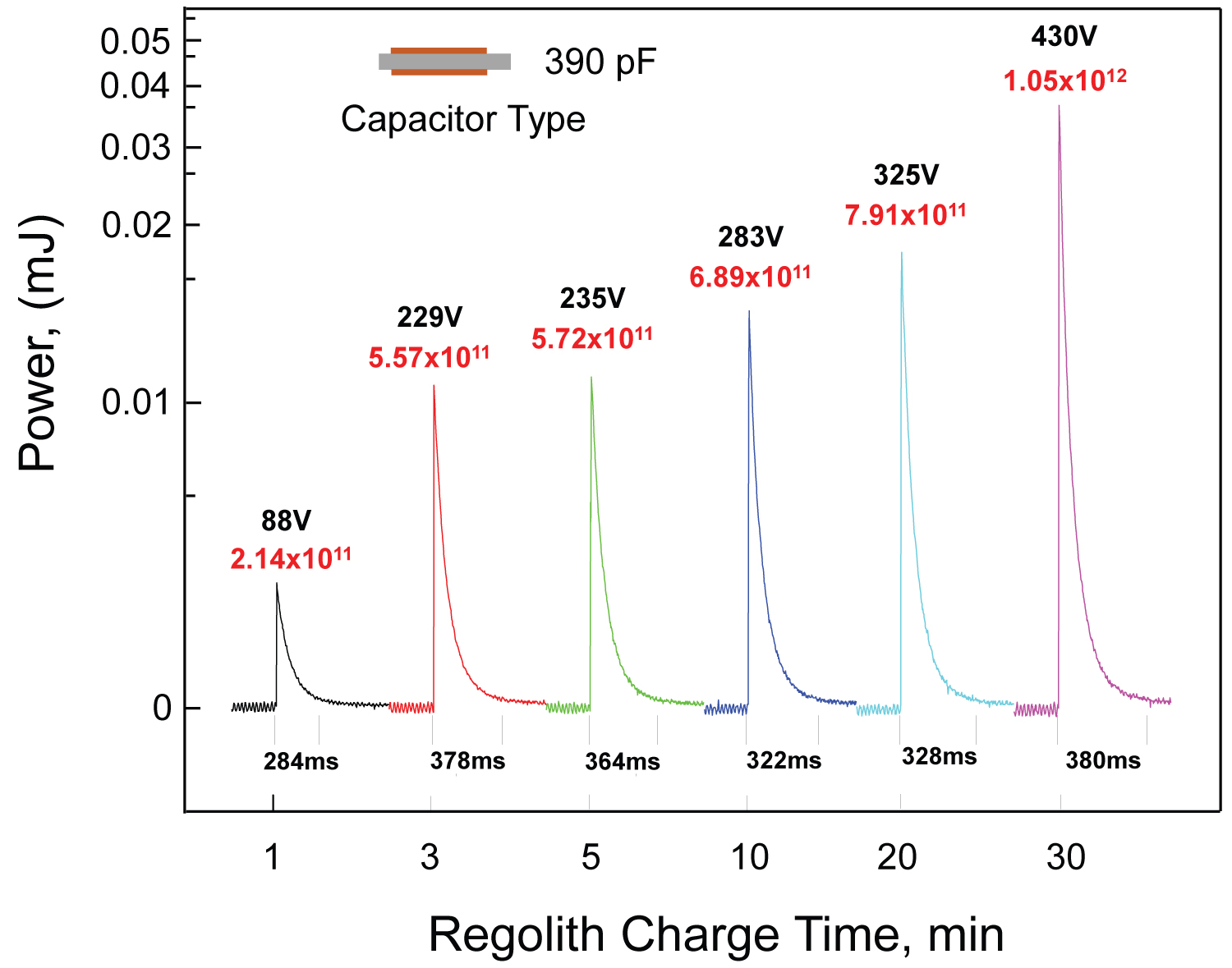
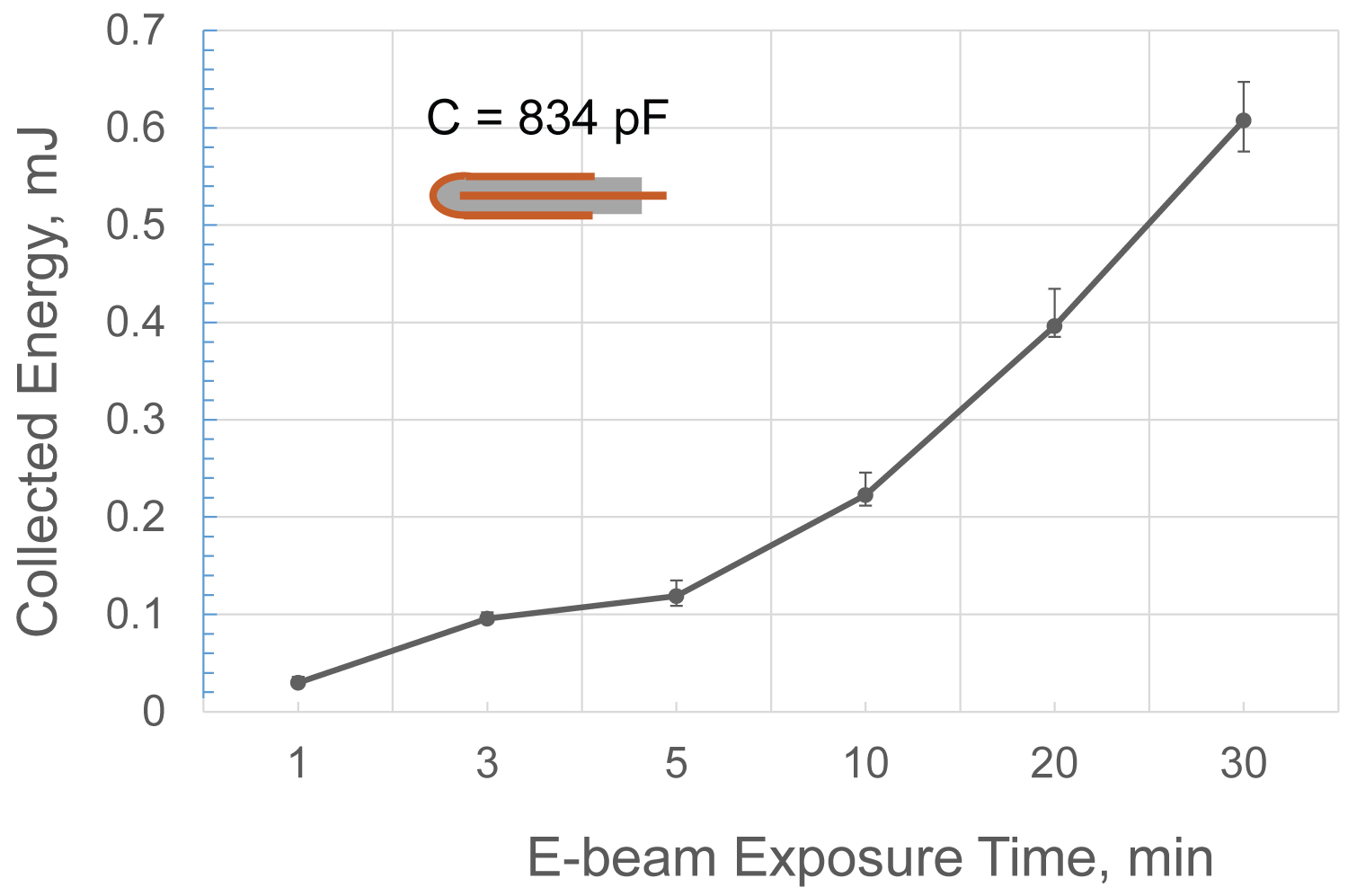
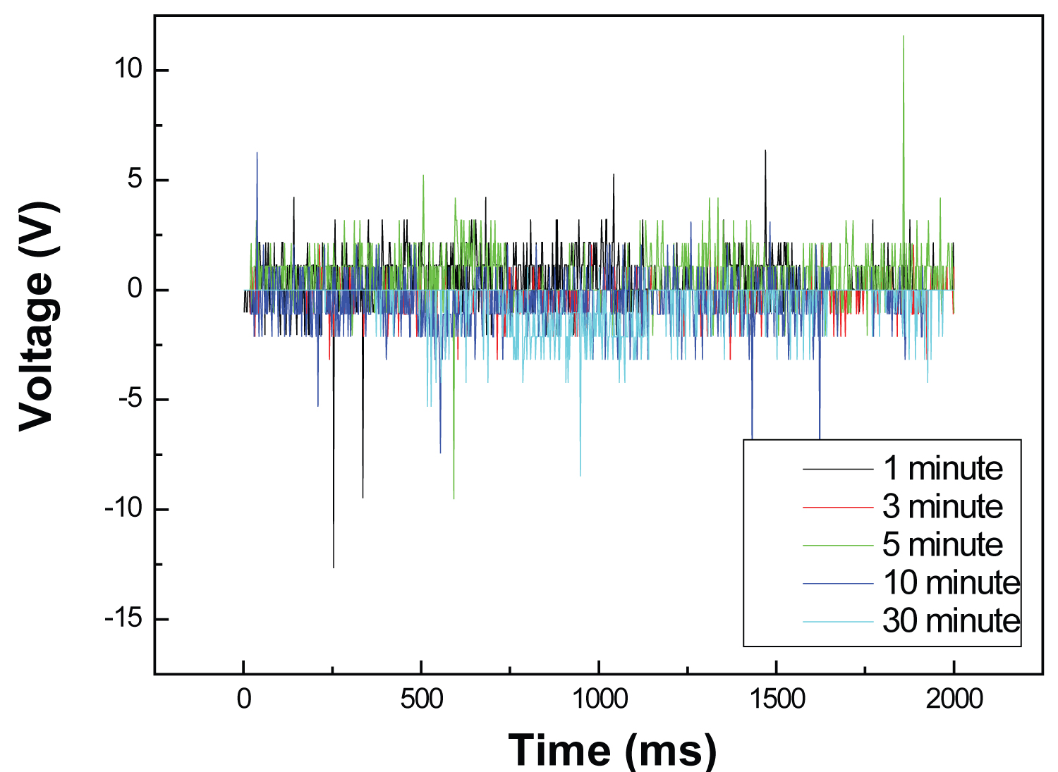
After the simulant was charged in vacuum by the incident electron beam and VUV for various selected exposure periods, the electron-beam was turned off and then a 390 pF capacitor, which is a single layer capacitor as shown in the inset of Figure 5, was run over the simulant surface to collect the charges. Figure 5 shows the series of measured maximum charge voltages and collected number of electrons for the cases of electron charge period from 1 minute to 30 minutes by the flood e-beam source. It is very obvious that longer the simulant is charged, more number of electrons is deposited and collectable. Two numbers on each peak shown in Figure 5 indicate the capacitor voltage (in black) and collected number of electrons (in red). Each spike in Figure 5 displays quick decay quickly because of fast leak rate through the side edges of capacitors. The time intervals indicate the leak times when collected electrons leaks out quickly through the open edges of capacitor on each run-cycle for charge collection test. The rapid loss rate is mainly due to the leakage current from the open edges all around the laboratory fabricated capacitor array. Because the edges of laboratory-made capacitors were not electrically sealed and insulated, the electrical hold-off voltage is very low and the discharge by leakage is pretty much dominant. We anticipate that the optimized leak-proof fabrication of capacitor array would show the higher peak and stability of charge with very slow leak rate. Accordingly, higher gain of charges than measured is anticipated because of the charge accumulation by leak- proof seal and insulation. If the capacitor array has a better leakage-proof seal and insulation, the charge peaks will have much higher peaks than those plotted in Figure 5. The experimental results with a capacitor array that has the capacitance of 3190 pF are shown in Figure 6. The peak charging voltages and collected energy were measured for each case of charging time starting from 1 minute to 30 minutes. The charge collections from the simulant for the E-beam charging cases with 20 minutes and 30 minutes, respectively, were at almost the same level around 1000V. In this case, the number of electrons collected was N e =2 × 10 13 . Based on the capacitance and the charging voltage, the energy harvested is 1.6 milli-joule (mJ). However, the home-made capacitor array has severe leaks through all around the unsealed edge of capacitors because of low hold-off voltage. The thickness of dielectric medium sandwiched by two conducting plates at the top and bottom is so thin that its capacitive hold-off voltage is also very small. That’s why most of capacitive charges shown in Figure 6 are rapidly decayed. A single strip of a wrapped plate capacitor with 834 pF (see the inset of Figure 7) was selected for test. This capacitor is the fifth one from the right hand side which is pointed by a blue-color arrow in Figure 3. In Figure 7, the energy collected by the 834 pF capacitor is almost proportional to the amount of electrical charges deposited and kept on regolith simulant particles with dangling bond along with the exposure time to a incident stream of E-beam. It is obvious that a longer period of exposure means a more charge density of electrons is deposited on regolith simulant. The test of energy collection by this capacitor was repeatedly performed at each exposure time to show any bias errors. At short exposure time by E-beam, the measured amounts of collected energy were not widely scattered. This is probably due to the facts that the charge distribution on regolith simulant at low exposure or low charging time is kept stable without much repulsive disruption of charged electrons, the electron leakage rate of the capacitor was small at the low-level capacitive charge, and the charge density of capacitor after low level charging is still less than the hold-off voltage of unsealed side strip of capacitor. Each point of the data indicates the peak energy stored in the capacitor before leaking. For the array of capacitors shown in Figure 3, the peak voltages and the numbers of electrons collected by the capacitor array were varied from the electrically charged regolith simulant for each case of 1 minute through 30 minutes charging time by E-beam. Figure 8 shows the measured leak rates of a capacitor array with capacitance of 9357.4 pF after charged to 1,200V. The total charged energy is 6.74 mJ, but discharged by fast drain over 1250 ms as shown in Figure 8.
The charge collection rate is determined by the speed of the capacitor array carriage and the contact area of simulant. When the lunar simulant was charged with the e-beam flux of 10 keV and 0.620 mA for 3 minutes, the capacitor array was then dragged over the simulant soil with run time intervals of 3.25, 3.00, 2.96, 2.71, and 1.29 seconds, corresponding to velocities of 3.1, 4.5, 6.0, 7.3, and 8.7 cm/s, respectively. Table 2 shows the measurement data of collected charge voltage and number of collected electrons based on the test parameters: E-beam source with 10 keV and 0.783 mA emission beam current; vacuum at 8.6 × 10 -6 torr; E-beam illumination time of 3 minutes; carriage moving distance of 40.6 cm; and average grain size of simulant of 367 nm. The measured voltages are plotted against the speeds of the charge collector as shown in Figure 9. An expected linear trend of charge collection from 500 V to 300 V along with the speed of collector is shown by a sold line in Figure 9. The charging voltages are dropped from about 500V down to 430V, 375V, and 275V, correspondingly, along with increasing the velocity from respectively. The results show clearly that the faster the speed, the smaller the charge collection. However, actual measured data for charge collection based on selected speed shows rather a curvy nature (see the dots in Figure 9). This is most likely due to the fact that the E-beam flux is not geometrically uniform over the area of exposure.
Figure 10 shows a picture of E-beam exposed sapphire substrate which shows hot spots (dark reddish color spread) developed on it. The hot spots are an indication of uneven E-beam profile. A dark reddish spread indicates unevenly exposed sapphire substrate by E-beam. The reddish spots are due to the spiky nature of the E-beam flux by the bunching and tearing modes of E-beam instability. Based on visual observation, the E-beam profile was found to vary slightly on each measurement interval. Another major deviation is probably caused by their regularity in contact with the charged simulant during the charge collection.
To determine the charge collection rate, the lunar regolith stimulant was charged for 3 minutes by the electron beam which was set to 10 keV, 0.624 mA (emission). The voltages, accordingly the charge collection, were also measured at travel distances while the collector ran at a constant velocity of 7.3 cm/s. The voltages measured along the passage of the collector were 275, 380, 370, and 1,050 volts at the collector locations of 17.8, 25.4, 33.0, and 40.6 cm, as shown in Figure 11. The increasing trend indicates that the charge is continually collected and built up with travel distance.
Typically, it was observed that the very fine particles were levitated and attached to the wall of the test chamber whose vacuum pressure was kept at 10 -5 to 10 -6 torr. Although it was not possible to directly measure levitated particles by the installed video camera and laser scattering measurement system (see Figure 2), the chamber wall, camera, and capacitor array carriage were coated with dust as shown in Figure 12a. A sample of the simulant placed in the scanning electron microscope (SEM) showed particle movement from the electron beam charging as shown in Figure 12b. Similarly, the attachments of charged particles to mechanical parts of equipment were also reported by Kawamoto, et al. in 2011 [26].
Mitigation of fine dust and electrostatic accumulation from lunar regolith had imposed serious problems, such as abrasiveness on bearing, pervasiveness as coating on seals, gaskets, and lenses, and physiological effects on astronauts and robotic systems for Lunar missions [47]. The basic mechanism of dust adherence is due to the electrostatic attraction of disturbed and levitated electrically charged dust. Removal of adhered dust is not either trivial or readily doable. Some study shows a method of electrodynamic dust shield to repel the approaching dust particles by applying opposite charge and to remove the already adhered dust by dielectrophoretic forces [48,49]. Brush removal of already adhered dust was reported but not effective [50]. Prevention of dust mitigation can be done by neutralization of charged particle. The experiment carried out for the ESPG development also gives a benefit of dust mitigation by charge neutralization. Figure 13 shows the charge collected during the backward track of capacitor array is almost negligible to count in measurement. Since the forward track has collected most of charges, the backward track does not have many charges to collect.
Design for a Power Collection System
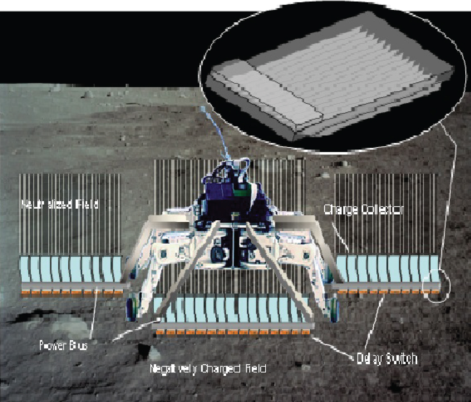
Based on the experimental study discussed above, an array of capacitors was designed for rover application as shown in Figure 14 to collect the charge and at the same time to neutralize electrostatically charged regolith. In its final form, an array of single-layered, flat capacitors securely attached to a motorized lunar buggy would collect the charge from the lunar surface. The charge collector consists of a thin-film array of capacitors that are continuously charged and sequentially discharged using a time-differentiated trigger discharge circuit to produce a pulse train of discharge for DC mode output as shown in Figure 15 and Figure 16. An array of flexible capacitors, as previously shown in Figure 2, was designed to freely run over any rugged objects on the lunar surface. To optimize charge collection, metal-insulator-metal (MIM) capacitors can be fabricated with a physical vapor deposition process to control the thickness and maximize the capacitance. The capacitor strips also could be configured in an array with several electron capture blades that rake through the lunar soil. Several of these arrays can be linked together for wider coverage.
Figure 17 shows a circuit for electrostatic power generation that collects and converts capacitively charged electrons into modulated power with differential drain delay described by the equivalent circuit in Figure 15 and Figure 16. This circuit consists of a variable DC-DC transformer, a rectifier, a smoothing capacitor, and a regulator, and can be duplicated and combined with several other charge collection capacitors in order to generate a steady DC power output.
Studies made on the charge density of lunar soil predict about several thousand volts of electrostatic charge [20,22]. One simulation study done at NASA Kennedy Space Center predicts the negatively charged lunar soil can reach a voltage of about 700 [24]. A report by Timothy J. Stubbs, et al. [34] discusses triboelectric charging, a transfer of charge from the body to another as they contact each other. His estimate is that approximately 10 5 electrons are gained through inter-grain contact by an individual grain of lunar soil (diameter ≈50 µm). For a 10-blade collector, with each blade 5 cm high and 30 cm long (2 collection sides = 300 cm 2 ) the charge accumulation can be estimated. For the purpose of a design study on a charge collector that will run on the lunar surface, it was assumed that a lunar dust grain has been charged and accumulated approximately 10 7 electrons over 4 billion years of exposure. The charge collector, with 10 blades plus array base, would have a total contact area of about 3300 cm 2 and would make contact with 132 × 10 6 grains (maximum) of lunar soil. In this case, the total maximum charge transfer at any given moment would be 132 × 10 13 electrons, corresponding to a charge of 21 × 10 -3 C/s or 21 mA for a 10-unit array moving at 30 cm/s. Utilizing an open circuit voltage of 700V [34], the total maximum theoretical power which can be harnessed from the lunar soil would be 5.88W per array. The parameters used for the estimation of ESP module performance are listed in the (Table 3). The results from this estimation are tabulated in Table 4 to compare with high efficiency multi-junction photovoltaic cells. From the results in Table 4, there are some advantages of ESP modules as compared to the multi-junction solar cells. The power collected by the ESP module appears very attractive since it can be also used during the approximately two weeks of lunar nights where sun light is not available. The fabrication of ESP modules is fairly in expensive as compared to the multi-junction solar cells. The only drawback of ESP modules is a short life expectancy since the ESP modules are being dragged on the lunar soil surface. A short useful life of ESP modules can be compensated by replacing the damaged ones with spare modules. The damaged modules can be readily replaced mechanically with spare modules. The ESP module is very light weight due to its thin-film structure that allows for several of them to be carried as spare parts for replacement.
One of the key issues that must be considered for ESPG application on the Moon is the formation of power circulation loop that includes the electrical ground. The regolith bed of lunar surface is electrically non-conductive that cannot be used as a ground of electrical systems. The bed-rocks of the Moon are known to have the ground potential, but actually not measured or estimated the ground potential. Also for mobile system, the accessibility to bed-rocks is very unlikely because most of lunar bed-rocks are populated in depth of regolith bed.
Currently, the ESPG model discussed here requires electrical ground for a power circuit but is not estimated with electrical ground. It is noted that development of Lunar applicable electrical ground is underway by the authors’ laboratory at NASA Langley Research Center.
Conclusions
Lunar surface electrification may be a concern for exploration, both directly and via its effect on lunar dust. Harvesting of electrostatic charges from lunar simulant soil was successfully demonstrated. The laboratory setup allowed charging of lunar regolith simulant with a flood e-beam in vacuum and collection of the accumulated charge. Collection of the charge was accomplished with the capacitor array at various speeds and travel distances to verify the feasibility of a similar setup on a lunar vehicle for lunar power generation and charge neutralization. Although levitation of charged fine particles of simulant was not measured or observed directly, the adhesion and accumulation of dust on the vacuum chamber walls and the movement of particles under charged field within the SEM suggest that levitation occurred in the test chamber. Studies of this kind will allow us to determine how to intelligently adapt and utilize the harsh environment of the Lunar surface to a beneficial asset. Also, based on the reported data and experimental results, a concept of a Lunar rover equipped with a carriage of capacitor arrays to collect the charge was designed, and the overall performance and power collection was estimated. It was found that the power generation from the electrostatic power generator (ESPG) was comparable to the output from high performance solar cells when the same size of collector or interacting surface areas are compared. Such a device concept, ESPG, studied here clearly shows the benefits of power generation and mitigation of charged particle by neutralization.
Acknowledgments
The author and coauthors are employed by a U.S. government agency that directly funds this research. This research was performed under the NASA Langley Research Center’s Creativity and Innovation (C&I) Program from 2008 to 2010.
References
- Halekas JS, Lin RP, Mitchell DL, et al. (2005) Large negative lunar surface potentials in sunlight and shadow. Geophysical Research Letters 32: 1-4.
- Ball P (2007) Moon too static for astronauts. Nature News.
- Barker DC, Olivas A, Wang FB, et al. (2022) Adhesion of lunar simulant dust to materials under simulated lunar environment conditions. Acta Astronautica 199: 25-36.
- Farrell WM, Stubbs TJ, Vondrak RR, et al. (2007) Complex electric fields near the lunar terminator: The near-surface wake and accelerated dust. Geophysical Research Letters 34: 1-5.
- De Grossi F, Marzioli P, Cho M, et al. (2022) Trajectory optimization for the horyu -vi international lunar mission. Astrodynamics 5: 263-278.
- Caston R, Luc K, Hendrix D, et al. (2018) Assessing toxicity and nuclear and mitochondrial dna damage caused by exposure of mammalian cells to lunar regolith simulants. GeoHealth 2: 139-148.
- Pohlen M, Carroll D, Prisk GK, et al. (2022) Overview of lunar dust toxicity risk. NPJ Microgravity
- Horányi M, Walch B, Robertson S, et al. (1998) Electrostatic charging properties of apollo 17 lunar dust. Journal of Geophysical Research 103: 8575-8580.
- Calle CI (2011) The electrostatic environments of mars and the moon. Journal of Physics Conference Series 301.
- Halekas JS, Delory GT, Lin RP, et al. (2009) Lunar surface charging during solar energetic particle events: Measurement and prediction. Journal of Geophysical Research 114.
- Kawamoto H, Miwa T (2011) Mitigation of lunar dust adhered to mechanical parts of equipment used for lunar exploration. Journal of Electrostatics 69: 365-369.
- Kawamoto H, Uchiyama M, Cooper BL, et al. (2011) Mitigation of lunar dust on solar panels and optical elements utilizing electrostatic traveling-wave. Journal of Electrostatics 69: 370-379.
- Dove A, Devaud G, Wang X, et al. (2011) Mitigation of lunar dust adhesion by surface modification. Planetary and Space Science 59: 1784-1790.
- Liu Y, Taylor LA (2011) Water on the moon. Acta Petrologica Sinica 27: 579-588.
- Mukherjee NR (1979) Solar-wind Interactions with the Moon. Earth, Moon, and Planets 21: 307-317.
- Wang X, Schwan J, Hsu HW, et al. (2016) Dust charging and transport on airless planetary bodies. Geophysical Research Letters 43: 6103-6110.
- Wang YM (2010) On the relative constancy of the solar wind mass flux at 1 AU. The American Journal Letters 715: L121-L127.
- Summanen T, Lallement R, Quemerais E, et al. (1997) Solar wind proton flux latitudinal variations: Comparison between ulysses in situ data and indirect measurements from interstellar lyman alpha mapping. Journal of Geophysical Research Space Physics 102: 7051-7062.
- Kellerman AC, Shprits YY (2012) On the influence of solar wind conditions on the outer-electron radiation belt. Journal of Geophysical Research 117.
- Reeves GD, Morley SK, Friedel RHW, et al. (2011) On the relationship between relativistic electron flux and solar wind velocity: Paulikas and blake revisited. Journal of Geophysical Research 116.
- McComas DJ, Funsten HO, Fuselier SA, et al. (2011) IBEX observations of heliospheric energetic neutral atoms: Current understanding and future directions. Geophysical Research Letters 38.
- Zimmerman MI, Farrell WM, Stubbs TJ, et al. (2011) Solar wind access to lunar polar craters: Feedback between surface charging and plasma expansion. Geophysical Research Letters 38.
- Halekas JS, Delory GT, Brain DA, et al. (2007) Extreme lunar surface charging during solar energetic particle events. Geophysical Research Letters 34.
- Saito Y, Yokota S, Tanaka T, et al. (2008) Solar wind proton reflection at the lunar surface: Low energy ion measurement by MAP-PACE onboard SELENE (KAGUYA). Geophysical Research Letters 35: 1-6.
- Jordan JP, Stubbs TJ, Wilson JK, et al. (2014) Deep dielectric charging of regolith within the moon's permanently shadowed regions. Journal of Geophysical Research: Planets 119: 1806-1821.
- Snowden SL, Collier MR, Kuntz KD, et al. (2004) XMM-Newton observation of solar wind charge exchange emission. The Astrophysical Journal 610: 1182-1190.
- Aellig MR, Lazarus AJ (2001) The solar wind helium abundance: Variation with wind speed and the solar cycle. Geophysical Research Letters 28: 2767-2770.
- Champlain A, Mateo-Velez JC, Roussel JF, et al. (2016) Lunar dust simulant charging and transport under UV irradiation in vacuum: Experiments and numerical modeling. JGR Space Physics 121: 103-116.
- Stemovsky Z, Chamberlin P, Horanyi M, et al. (2008) Variability of the lunar photoelectron sheath and dust mobility due to solar activity. Journal of Geophysical Research 113.
- Abbas MM, Tankosic D, Craven PD, et al. (2007) Lunar dust charging by photoelectric emissions. Planetary and Space Science 55: 953-965.
- Abbas MM, Tankosic D, Craven PD, et al. (2010) Lunar dust grain charging by electron impact: Complex role of secondary electron emissions in space environment. The Astrophysical Journal 718: 795-809.
- Halekas JS, Delory GT, Lin RP, et al. (2009) Lunar prospector measurements of secondary electron emission from lunar regolith. Planetary and Space Science 57: 78-82.
- Forward KM, Lacks DJ, Sankaran RM, et al. (2009) Triboelectric charging of lunar regolith simulant. Journal of Geophysical Research Space Physics 114: 3.
- Sternovsky Z, Robertson S, Sickafoose A, et al. (2002) Contact charging of lunar and Martian dust stimulants. Journal of Geophysical Research: Planets 107: 15-1-15-8.
- Colwell JE, Batiste S, Horanyi M, et al. (2007) Lunar surface: Dust dynamics and regolith mechanics. Reviews of Geophysics
- Rennilson JJ, Criswell DR (1974) Surveyor's observations of lunar horizon-glow. The Moon 10: 121-142.
- Choi SH, Elliott JR, King GC, et al. (2006) Electrostatic power generator with capacitive charge collectors. NASA Invention Disclosure.
- Coenraads C, Denholm AS, Lavelle JE, et al. (1963) Electrostatic Power generators for space. Power Systems for Space Flight 917-939.
- Van de Graaff RJ, Compton KT, Van Atta LC, et al. (1933) The electrostatic production of high voltage for nuclear investigations. Physical Review 43: 149-157.
- Xie Y, Bos D, de Vreede LJ, et al. (2014) High-efficiency ballistic electrostatic generator using microdroplets. Nature Communications 5: 1-5.
- Boland J (2005) Micro Electrolet Power Generators. Ph.D. Thesis 56.
- Hyde WW (1990) Electrostatic energy field power generating system. U.S. Patent . 4,897,592.
- Kim BH, Bamhart BS, Kwon JW, et al. (2015) Electrostatic power generation using carbon-activated cotton thread on textile. Micro and Nano Systems Letters 3: 1-7.
- Breaux OP (1959) Electrostatic Power Generation for Space Propulsion. Electrical Engineering. 78: 1102-1104.
- Soliman MSM, Abdel-Rahman EM, El-Saadany, et al. (2008) A wideband vibration-based energy harvester. Journal of Micromechanics and Microengineering
- Kim DW, Lee JH, Kim JK, et al. (2020) Material aspects of triboelectric energy generation and sensors. NPG Asia Materials 12.
- Kobrick RL, Klaus DM, Street KW, et al. (2011) Defining an abrasion index for lunar surface systems as a function of dust interaction modes and variable concentration zones. Planetary and Space Science 59: 1749-1757.
- Calle CI, Buhler CR, Johansen MR, et al. (2011) Active dust control and mitigation technology for lunar and Martian exploration. Acta Astronautica 69: 1082-1088.
- Farr B, Wang X, Goree J, et al. (2020) Dust mitigation technology for lunar exploration utilizing an electron beam. Acta Astronautica 177: 405-409.
- Gaier JR, Journey K, Christopher S, et al. (2011) Evaluation of brushing as a lunar dust mitigation strategy for thermal control surfaces, 41 st International Conference on Environmental Systems.
Corresponding Author
Sang H Choi, Senior Scientist, Mail Stop 188A.NASA Langley Research Center, Hampton, VA 23681-2199, USA.
Copyright
© 2023 Choi SH, et al. This is an open-access article distributed under the terms of the Creative Commons Attribution License, which permits unrestricted use, distribution, and reproduction in any medium, provided the original author and source are credited.