Impact of a Change from an Aluminium- to a Composite-Type Aircraft on Wind-Assisted Aviation-Fuel Fire Dynamics - a Numerical Study
Abstract
This numerical study focuses on the impact of a composite-type aircraft on a large aviation-fuel fire in a moving fluid medium. A pyrolysis model over surface of condensed fuel and composite material is incorporated, allowing to investigate the roles of the wind conditions on fire growth, heat flux distribution and smoke products. The outcome of the study indicates that interaction between composite-type aircraft and fire environment combined with the influence of wind conditions affects dramatically the continuous flame shape and consequently, the distribution of the incident heat fluxes to the engulfed fuselage. An increase of wind speed results in an alteration of flame cover where the fire and fuselage are of comparable size. The highest toxic products such as carbon monoxide and soot occur on the windward side of the fuselage for a low wind speed, but on the leeward side of the fuselage for a medium or high wind one. The flame spread rate over a composite-type aircraft is almost equal in magnitude for a medium or high wind speed, but about a factor 4 increase of that to the low wind one. As a consequence, the fire power from a composite-type aircraft represents an increase of about 30% in comparison with that from aluminium-type one with a wind speed above 5 m/s.
Keywords
Pool fire models, Crosswind, Flame shape, Flame spread, Toxic product, Heat flux
Introduction
As a consequence of engine failure [1,2], the spilt aviation liquid fuel is volatilise to form a cloud of combustible mixture, with subsequent gas-phase ignition and establishment of a vapour cloud fire. Aircraft fire represents a major threat to the occupants and cargo due to a large quantity of aviation liquid fuel, and a greater heat feedback from large fully turbulent fires [3]. Regarding the new generation of aircraft, the substitution of aluminium-type fuselage by flammable composite material one with a composition of resin/carbon fibres, leads to a development of a fireball due to a larger heat release rate. In comparison with an aluminium-type airplane fire [1,2], the evacuation strategy and fire fighting in composite airplane fire is a delayed effort. The burn-through time of a composite fuselage depends on the material composition of resin/carbon fibres, thickness, burning flammability, physical properties, etc. [4,5]. During a post-crash fire, burn-through of the composite fuselage does not occur within 3 minutes [5]. Ignition and propagation of composite-type aircraft fires are complex phenomena involving several scales defined from the smallest to the largest. The smallest scale is that a composite material particle with the main physical effects involved such as the fusion and thermal degradation [5]. The largest scale is the relevant scale to develop a buoyancy-controlled thermal plume in cross-wind [2].
Intensive research has been carried on interaction between a flame and a cross-flow [6,7] in terms of the ratio between buoyant and inertia forces in assessing if the flame is controlled by a natural or forced convection. Putman [7] investigated the behaviour of small fires, indicating that an increase of the longitudinal ventilation rate enhanced the visible flame length where the gas temperature is above 500 ℃. Most of the existing literature [8-11] on the dynamics of fires have also investigated pulsation or puffing under cross-wind conditions in a reduced-scale. The study of Russel [12] demonstrated the alteration of the flow field and the related influence on the fire physics when a small cylinder as compared to the fire, is fully engulfed by the flames. It is well known that reduced-scale tests do not necessarily reflect the behaviour of a full-scale fire due to large contribution by radiation associated with fire growth rate. A remarkable proportion of the work has thus looked specifically at large-scale pool fires [13-17] which imply poor entrainment, therefore enhanced soot production. By means of Gardon-gauge-type radiometers, the analysis of Gregory [13] showed that a maximum heat flux on the bottom of the horizontal cylinder engulfed in luminous flames, and minimum on the top. The Birk correlation [14] predicts that the highest heat fluxes are at the top and the values decrease along the periphery to the underside of the cylinder. The occurrence of large fires which engulf objects was experimentally and numerically studied by Gritzo [15]. Tests were conducted by Keltner [16] to simulate fuel spill fires that might occur under the wing of a transport aircraft. By means of both radiometers and thermocouples, a considerable effort has been made by Suo-Anttila [17] in conducting a full-scale measurement of the temperature and heat flux distributions with the presence of a fuselage-sized cylindrical object engulfed in a large aviation fuel fire subjected to various winds. Nevertheless, large-scale liquid hydrocarbon pool fires are difficult to analyze experimentally because of the sheer scale of the fire. The computations effort of large pool fires by using type turbulent model in cross-flow [18] was driven to assess the complex geometry or physics.
Maritime accident regarding fire and explosion events is also dealt with carefully, allowing to identify the most significant causes of accidents such as hot work, electric arcs, static electricity, and combustible gas accumulation in the cargo tank [19]. A hybrid model was developed for human-factor analysis of engine-room fires on ships by taking into account the wide range of both sources of fuel and sources of ignition within the engine room [20]. A new framework which is based on grounded theory, fault tree analysis and Bayesian network, was proposed for identifying critical risk factors in ship fire accidents [21]. The recent cases of ship fires explosions due to lack of safety awareness were analysed [22], suggesting the necessity to research precise evacuation plans, develop ship structure/materials reinforcing fire resistance to secure more time for evacuation, and to enhance people`s safety awareness by implementing thorough safety training.
Although, modelling appears as the most promising technique in ship or aircraft fire accidents, presently analysis of toxic products as carbon monoxide and soot is primarily limited to characterization of large-scale fires in the absence of other influencing factors such as wind condition and engulfed objects, as described by Gottuk [23]. In this work, occurrence of large scale fire engulfing an aluminium- or composite-type aircraft is numerically studied to simulate fuel spill fires adjacent to the engine. The objectives of this work are to examine impact of a composite-type aircraft on the dominant hazards, such as fire growth, temperature, heat flux and smoke products like carbon monoxide/ soot under a variety of wind conditions. The availability of such numerical simulation can provide cost-effective alternatives by reducing the number of large-scale tests necessary to develop fire protection requirements or standards. An analysis has focused on flame spread and burning over a composite material surface of an aircraft exposed to an aviation-fuel fire in crosswind on a scale where both radiation and buoyancy are significant. A two-steps reaction model and smoke point concept for a fire model's treatment of soot formation are incorporated within Fire Dynamics Simulator (FDS) [24]. This makes Computational Fluid Dynamics (CFD) calculations of flame radiation in non-premixed flames of an arbitrary hydrocarbon fuel feasible, thereby retaining simplicity and minimizing computational expense. This approach has a profound influence on reliably predictions of mass burning of condensed fuels, flame spread and fire growth via thermal radiation. Large computer times are required to run these advanced models particularly for a full-scale, three-dimensional aircraft fire. The numerical model has been verified by comparing the computed temperature field and heat flux against the measurements from a full scale aviation-fuel fire engulfing a fuselage-sized cylinder [17], expressly to test the robustness and efficiency of the model [25]. We have attempted to provide an entirely tractable solution for engineering calculations such as aircraft fires.
Numerical Modelling
Physically-based models account for each mechanism of heat transfer and predicts not only the spread rate of the fire but also the chemical species. Advanced fire physics model, which is the subject of the current work, requires state-of-the-art submodels (combustion, multidimensional participating radiation, soot formation, heat transfer, condensed fuel vaporization, etc) which are coupled with the flowfield governing momentum solution. A physics-based continuum model is used, wherein governing equations for the various thermo-physical phenomena involved in fire are solved numerically. The finite-difference technique is used to discretize the mathematical representation of the reacting flow phenomena of interest here. A detailed description of the three-dimensional physics-based model can be found in FDS user guide [24] and references therein. This section provides only a summary of the physics-based model utilized in the current work.
Combustion via two chemical reaction steps
The combustion processes are governed by the convection-diffusion equations for the mass fraction, Yi, of the six major chemical species, such as CmHn, O2, CO, CO2, H2O and N2. The mixing-controlled combustion via two chemical reaction steps for CO formation is assumed.
In turbulent regime, the turbulence is so intense compared to the chemical time, allowing a perfect mix fuel and oxidant before the reaction occurs. In terms of limiting concentration of fuel or oxygen, this regime is referred as perfectly stirred reactor as in the EDC combustion model [24,26], and the local HRR is calculated as follows :
Here, i denotes the primary fuel and CO. The key mixing timescale, , is supposed to relate approximately to the three processes such as diffusion, subgrid-scale advection, and buoyant acceleration. The source term is multiplied by Heav(YO2-YO2,lim) which is zero when its argument is negative (YO2 < YO2,lim) and 1 when it is positive (YO2 > YO2,lim). Flame extinction occurs when the local oxygen concentration is below a critical value, YO2,lim which is evaluated as a function of specific heat, temperature and chemical composition [24].
Radiative heat transfer via soot formation
For a heavily sooting fire, the majority of the radiation in fire plume (> 90%) is derived from the visible part of the flame, where soot particles are radiating heat [3]. Soot production in fire plumes is a highly complex subject due to the spatially-varying formation and oxidation processes, the influence of turbulent fluctuations and strong temperature and fuel dependent effects. Nevertheless, a number of researchers [27] have had some success in identifying factors which allow simplified analysis. The current model use classic principle of smoke point to relate soot production to material properties. A fuel's smoke point is the maximum height of its laminar flame burning in air at which soot is not released from the flame tip [27].
A global soot formation model is incorporated into a turbulent flow calculation in a convection-diffusion equation for the soot mass fraction. Soot formation is assumed to be controlled by second-order homogeneous gaseous reaction processes, and thus, is expressed as a function of the mixture fraction, Z, and gas temperature, T, both affected by a pulsing behaviour in turbulent flames.
Here the temperature exponent and activation temperature are assigned. The parameter for differences in sooting behaviour of different fuels is the pre-exponential factor, Af, which is reversely proportional to its laminar smoke point height which has been measured for many fuels [27].
A radiative transfer equation is solved by using a discrete expression adapted to a finite volume method [24].
As the radiation spectrum of soot is continuous, it is assumed that the mixture of soot and gas behaves as a gray medium with a mean absorption coefficient, , used in Eq.(5). A narrow-band model (RadCal) has been implemented in FDS [24] for the calculation of the gray or band-mean gas absorption coefficient. The effect of soot concentration on radiation is included by adding the radiation coefficient of soot into that of gas [24].
Phase coupling conditions
The thermal degradation of the solid phase of composite type as well as the combustion of the gaseous pyrolysis products require the development of specific chemical models for the composite material. Advanced measurements on temperature-dependent, composite material property information on thermal conductivity, density, heat capacity, heat of pyrolysis and reactions Arrhenius parameters would require an extensive experimental effort [4,5]. Furthermore, each material component in the composite fuel may undergo several competing reactions, and each of these reactions may produce some other solid component (residue) and gaseous species. More comprehensive and complex models would be prohibitive in the framework of large CFD problems. A pyrolysis process of the charring materials gives rise to a charred surface layer and its thickness increases with time. The charred surface layer shields the heat flux and thereby limits the rate of fuel gas production. The pyrolysis model of the composite material needs effective material properties for properly estimating the thermal degradation of solid fuels in a fire situation, including evaporation, charring and internal heating [28,29]. The development of more complex reaction mechanisms for the composite material is challenging due to the high complexity of fire spread dynamics that arises from the interaction between solid and gas phase, and the corresponding physical - chemical processes (e.g. pyrolysis).
The current model to the field modelling of pyrolysis process includes the material properties, heat transfer, chemical kinetics, soot and turbulence effects on fire spread over condensed fuel surface. A thermal equilibrium over the surface of the virgin condensed material is used, and the pyrolysis rate is calculated via a mass balance across the interface [30] as follows:
The mass transfer coefficient induced by convection, hm,conv, is defined as,
where is the density, the thermal diffusivity, and L the local length scale. The Nusselt and Reynolds numbers are defined respectively as,
and
The empirical constants are given as m = 0.037 and n = 4/5 for the Reynolds number beyond a value of 3 × 10⁵, and m = 0.664 and n = 1/2 for Re below that value.
The mass transfer coefficient controlled by radiation, hm, ray, is expressed as,
Here, Cp denotes the gas specific heat, Ts the surface temperature of condensed fuel, and Tg the gas temperature. The radiation heat flux is obtained from the radiant intensity [24], I, by solving a radiative transfer equation (Eq.5) associated with a mean absorption coefficient in a gray medium. For situations where the condensed fuel is a diffusively reflecting and emitting surface, the radiant intensity over the burning surface is calculated by using the following expression [24],
Here, denotes the surface emissivity, the solid angle and rs the direction vector of the intensity.
The mass transfer number, B, in combustion system is defined as follows [30]:
Here is the stoichiometric fuel/oxygen ratio, Hc the heat of combustion, Lv the fuel latent heat and the local oxygen mass fraction. The gas and condensed fuel specific heats are denoted respectively by Cpg and Cpc.
The B-number approach as Eq.(11) is employed because its robustness and efficiency has been tested [30]. Even with such approach, the number of properties needed is staggering and we lack the ability to accurately quantify here through bench-scale experiments. Table 1 presents the temperature-independent material property found in literature for the liquid fuel (kerosene) [30] and the composite material [4,5]. However, the specific composition of aluminum about its purity and composite materials about kind of the resin/fiber and its content is unknown due to industrial confidentiality, e.g. AirBus. All the parameters in Table 1 are used in the FDS [24] input file. In fact, the composite content of aircraft is generally between 15% and 55%. However, we lack the ability to develop a more complex pyrolysis model to take into account the influence of composite content on its fire behavior.
The condensed fuel is assumed to be thermally-thick, a one-dimensional heat conduction equation for the material temperature is solved [24]. The surface temperature, Ts, is affected by gains and losses with a heat balance across the interface:
Here, is the thermal conductivity of condensed fuel.
Results and Discussion
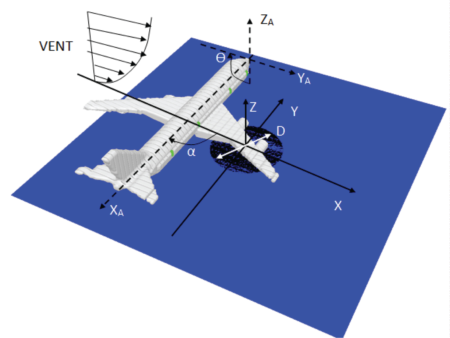
Schematic diagram of an aircraft fire, and coordinate system in the numerical simulation are shown in Figure 1. The atmospheric condition, characterized by fluctuations in wind speed and direction, can't be taken into account in the current simulation. The aircraft orientation relative to the external post-crash fire in crosswind, area of spill and volume of fuel are the important parameters. Therefore, scenarios of an aircraft post-crash fire are highly variable because of the extremely varied nature of wind conditions. Therefore, the influence of deviation in the wind speed on the behavior of the fire is studied by taking into account a speed range of 0-10 m/s. The effects of aircraft orientation relative to the wind direction, characterized by an angle α that varies from 0 to 360° (cf. Figure 1), on the heat flux over the fuselage skin are taken into account.
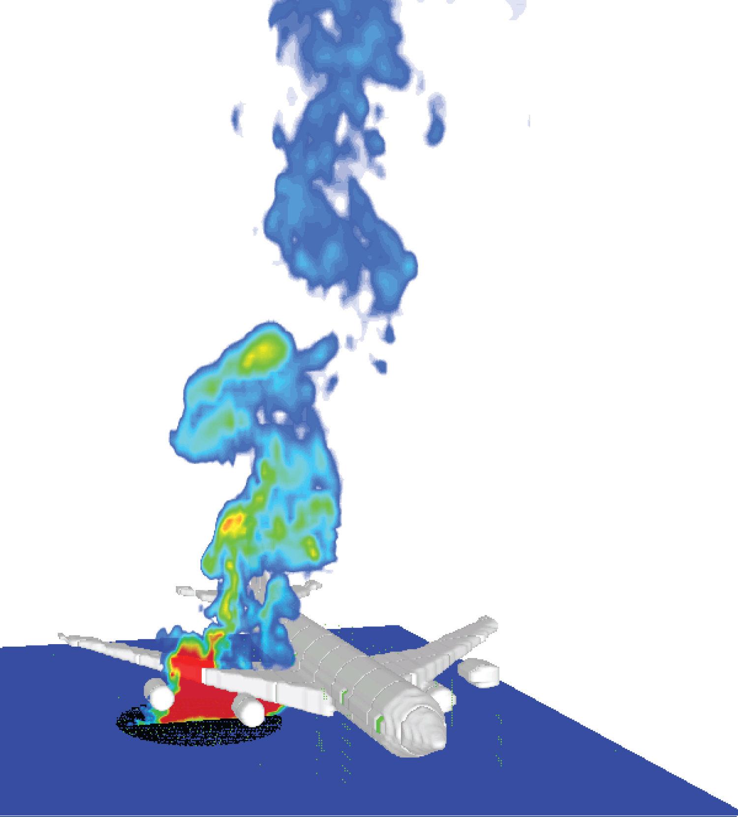
The calculations were performed using a computational mesh, which was made up of 200 × 200 × 250 cells with overall dimension of 90 m in length (x), 90 m in width (y) and 100 m in height (z). The grid is locally refined with extra grid points being added in strong shear stress zones, such as near the pool fire surface and in the wake region around the aircraft. Along the length, x, cell sizes start at 0.15 m around the pool fire, and stretch to about 1 m at the free boundary. In the z direction, cell sizes are approximately 0.1 m in the vicinity of the burning zone and stretch to about 1.2 m near the free boundary. A uniform grid is used with a cell size of approximately 0.45 m in the transversal direction, y. Upon encountering the perturbation induced by an aircraft in crosswind, the boundary layer probably changes rapidly from transition into a fully turbulent one. The viscous sublayer is critically dependent on the near-wall model due to important viscous effects. An extremely small grid size (mm) is required to fully resolve the turbulent boundary layer and the complex flow instabilities in the wake around aircraft for the high Reynolds number flow, making practical fire simulations difficult. In the present work, the computational nodes immediately adjacent to a wall are located in the fully turbulent region and this simplicity allows faster computations and by this a higher spatial discretization and an increase of the resolved part of the fire oscillation. Besides, predictions of the most dominant radiative heat transfer are generally less sensitive to the near-wall turbulence model. It was found that the mildly stretched grid system with a moderate computational domain offered the best tradeoff between accuracy and cost. With the use of a highly compressed grid system, build-up of numerical error could produce spurious results over the course of a LES calculation due to commutation of the filtering operation. Up to now, investigations of the large-scale fire are limited to computations on relatively coarse meshes [18,25]. Instantaneous view of the predicted thermal plume at a wind speed of 2 m/s is illustrated in Figure 2. Oscillations of the fire plume due to air entrainment variation and flame flicker correspond to hot gases puffs burning [8-11,31], consistent to a real aircraft fire situation. Note that during a post-crash fire, a burn-through time of the fuselage within 180 seconds is used to guide the evacuation strategy, and thus, taken into account as a physical duration in the numerical simulation.
Heat flux distribution
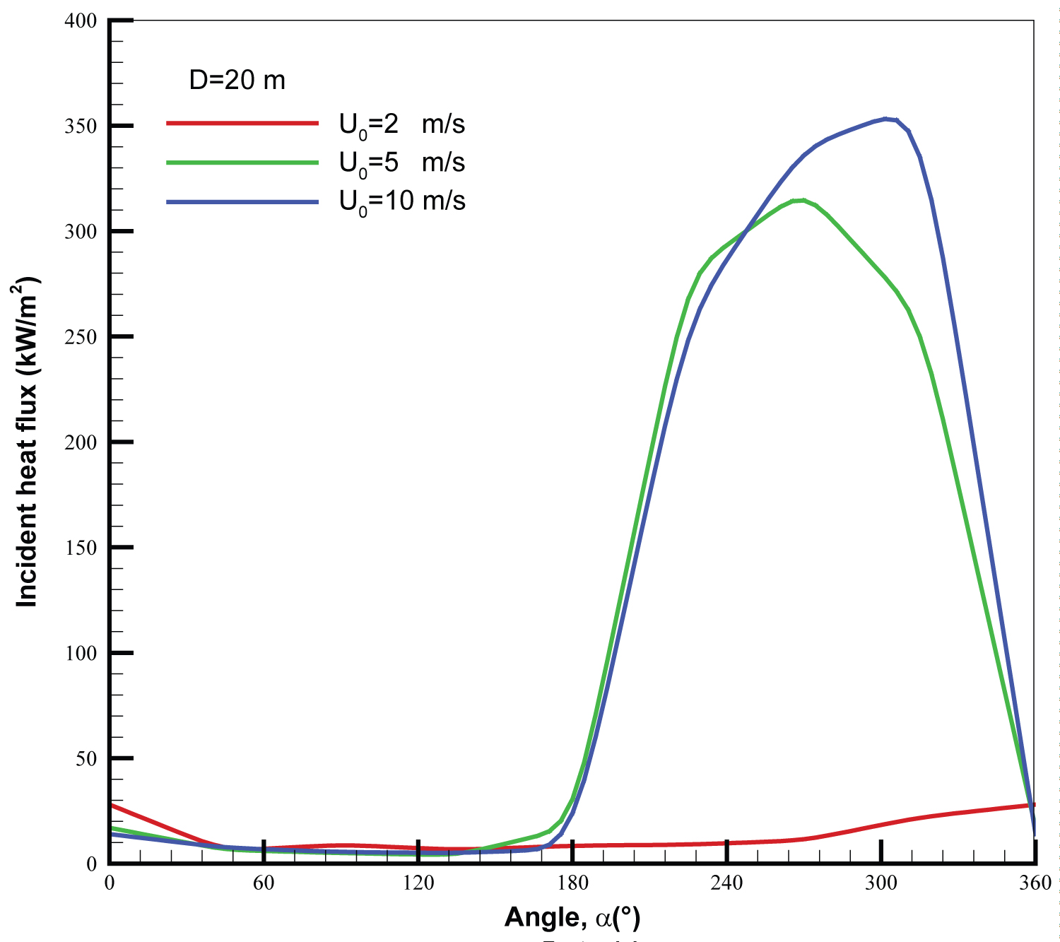
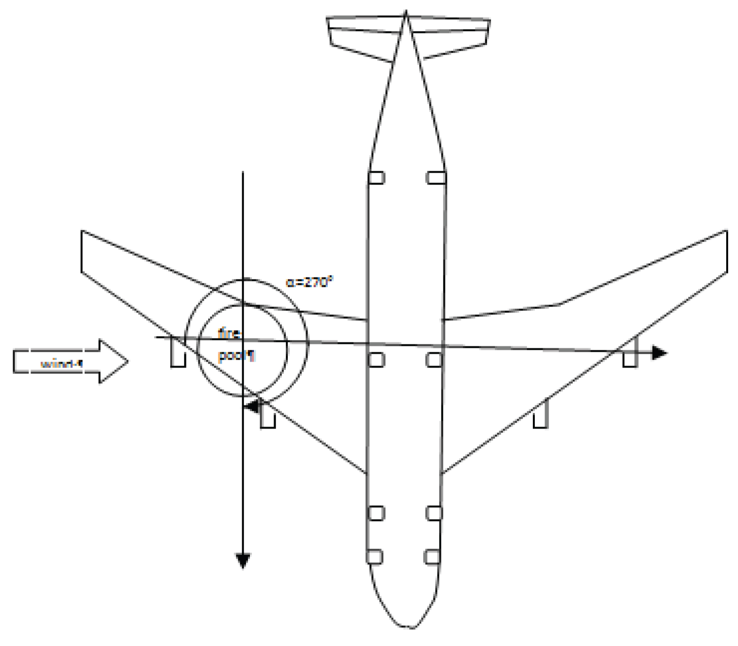
For the large scale fire, radiation flux seems the central and dominant mode of heat transfer [3], convection flux plays a second role [32]. The radiation heat flux to the surrounding aircraft skin depends mainly on three factors: 1) The flame volume and its temperature level; 2) The concentrations of gaseous and particulate soot emitting species; 3) The view factor from flame to the exposed fuselage skin. Changes in the maximum heat flux to the fuselage skin as a function of the orientation of aircraft relative to the wind direction are shown in Figure 3. Radiative heat transfer is combined with wind-enhanced, aircraft-induced turbulence and global flame zone redirection. Thus, the wind direction combined with its intensity directly affects the view factor from the flame to the fuselage skin, and consequently, has a pronounced impact on the flame-surface heat flux over the fuselage skin. When the wind direction changes from 0 to 180°, the aircraft is located upstream the pool fire. In this case, the flame is directed far away from the aircraft by the crosswind and the peak in heat flux to the fuselage skin is minimum. When the aircraft is located downstream the pool fire (α > 180°), i.e., the flame is directed towards the aircraft by a crosswind, the peak in heat flux to the fuselage skin increases sharply. Interaction between the pool fire and the aircraft becomes the strongest when the aircraft moving direction is perpendicular to the crosswind, as schematized in Figure 4 for , with the highest heat flux for the wind speed above 5 m/s [17]. A further increase of the angle results in a reduction in radiation flux mainly due to decreases of the flame to aircraft view factor. When the aircraft moving direction is parallel to the wind direction, the cold air flow, which is believed to act as a radiation shield, exists between the pool fire and the fuselage, and there is evidence of the lowest heat flux on the fuselage skin.
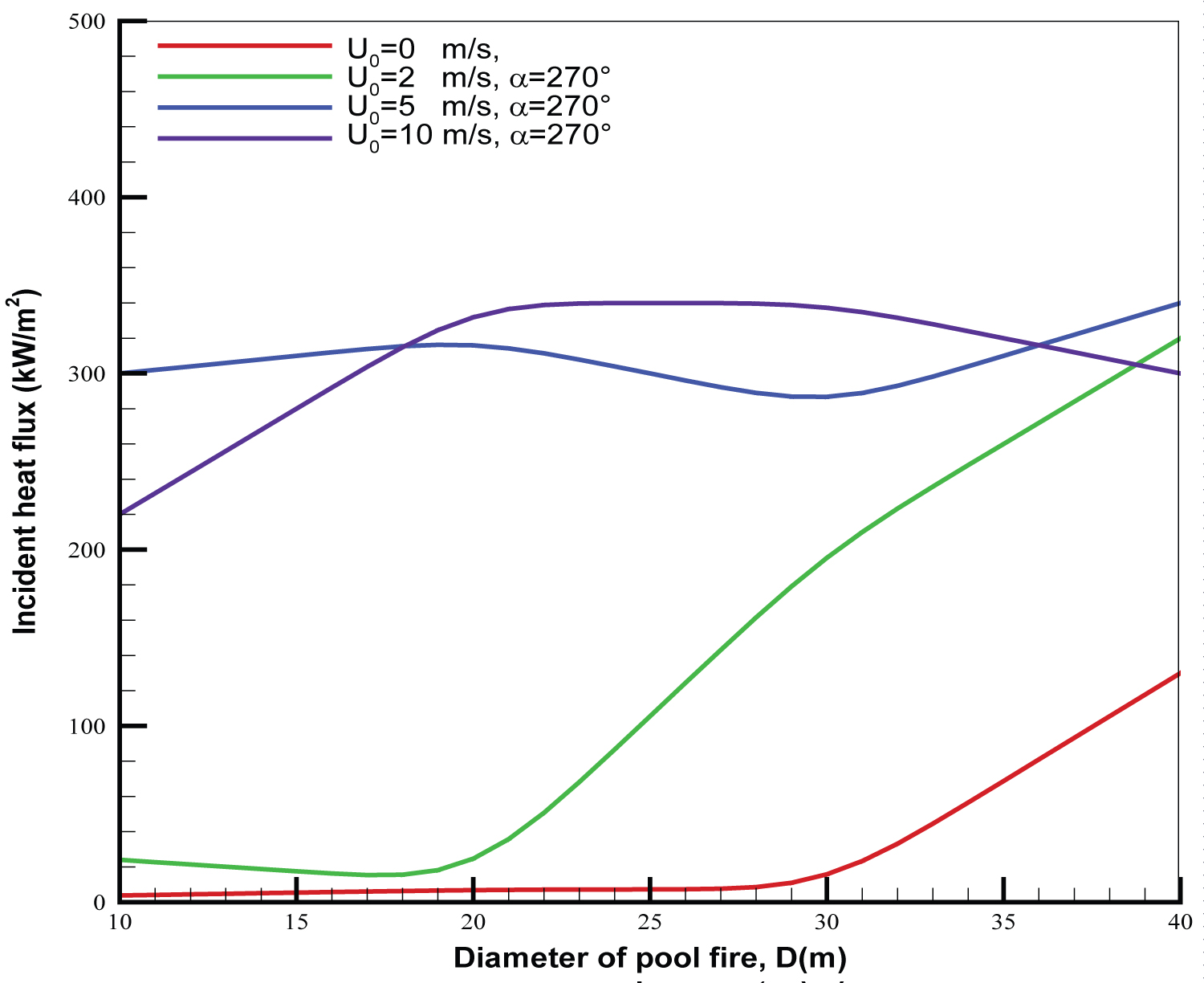
Since interaction between pool fire and aircraft is the strongest when the aircraft moving direction is perpendicular to the crosswind (cf. Figure 4), evolution of the peak in heat flux as a function of the pool size for various wind speeds in such situation is shown in Figure 5. Under the quiescent condition, since the pool fire is far away from the fuselage with a distance of about 25 m, the peak in heat flux on the fuselage skin becomes significant solely when the pool size exceeds 30 m in diameter due to an increase in the flame height and its volume. With a low speed of 2 m/s, the peak in heat flux on the fuselage skin becomes strong starting from the pool size of 20 m. The peak in heat flux on the fuselage skin even at a low wind speed of 2 m/s is almost tripled compared to that for a quiescent pool fire as the pool fire size increases to 40 m. For the mediate wind speed of 5 m/s, an increase of the peak in heat flux from 220 to 300 kW/m2 is brought about with an increase of the pool size from 10 to 20 m in diameter due to an increase in HRR. However, the peak in heat flux approaches an asymptotical value of about 340 kW/m2 for the kerosene pool fire once the pool size surpasses a critical dimension of 20 m in diameter regardless of wind intensity [17]. This is mainly due to the decaying of combustion efficiency with an increase of the pool size, which controls the temperature field through radiative heat transfer.
An orientation of and a pool size of D = 20 m are identified as the largest factors affecting the thermal environment. Thus, in the following section, such a particular situation (cf. Figure 4) is considered for investigating the effects of a composite-type aircraft on the major changes in the overall flame structure.
Flame spread over the skin of composite-type fuselage
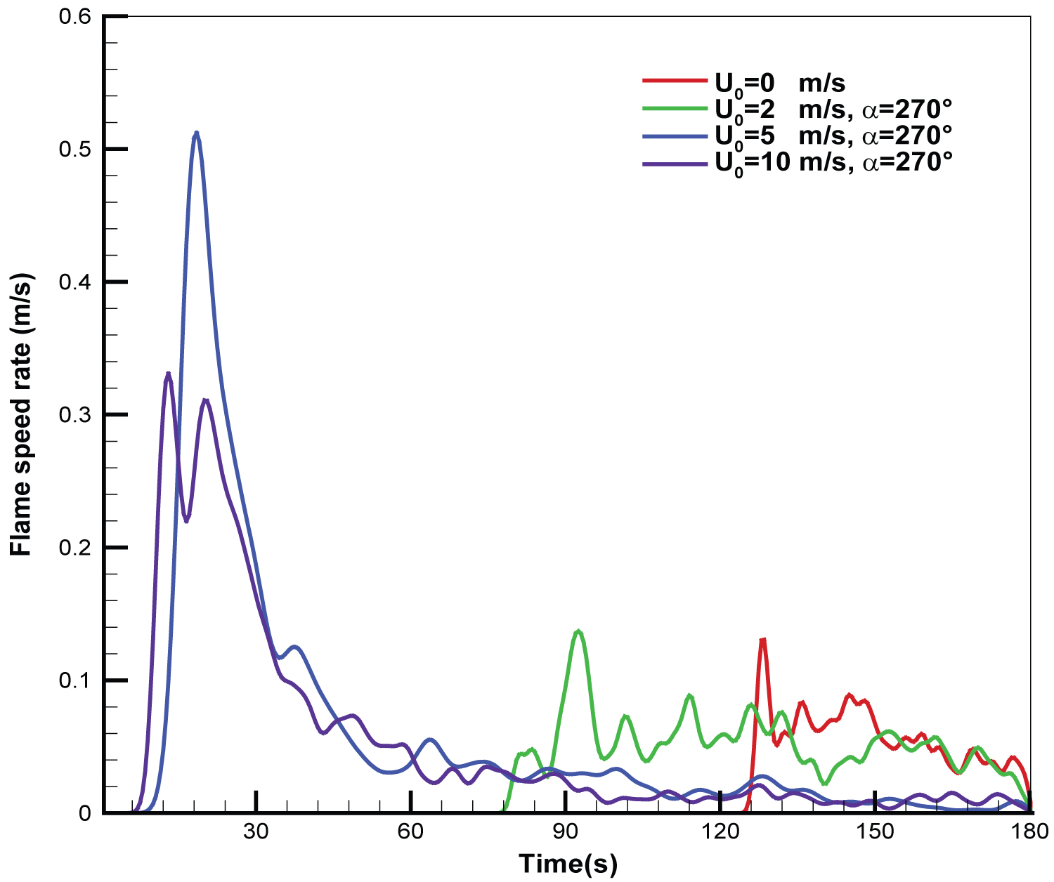
The flame front spreading is mainly governed by the heating rate of solid combustible materials to generate combustible gases via convective and radiative heat transfers [28,29]. The combustion reaction of flame front mainly occurs in non-premixed medium along the boundary layer between combustible material and air. A thermal layer containing the hot gases and soot is transported by natural or forced convection. By applying a heat flux up to 240 kW/m2, the flame spread occurs as a result of heating of the unignited part of composite materials to an ignition temperature of 390 ℃ at which the pyrolysis flux exceeds a certain threshold level, essentially dependent of air cross-flow. The gaseous products from pyrolysis of the composite materials in contact with air, ignite in the flammability limits. The time for the temperature at a given position over composite material surface to reach the ignition temperature is selected for the pyrolysis front arrival time, . Advancement rate of the pyrolysis front from zp to vs time interval gives the average flame spread velocity, Vp [33]. Temporal data of flame spread rate, Vp, for the different wind velocities are plotted in Figure 6, providing important information on events in the fire affected by the wind condition. The wind speed above 5 m/s bring about a direct impingement of the buoyant plume on the composite fuselage which tends to enhance the fire propagation. The results suggest that the flame propagation over the composite material surface occurs in two successive periods. In the first period during about 30 s corresponding to the preheating processes of the composite material, the flame spreads slowly over the fuselage skin with a mean value of 0.08 m/s. The second mode is evident from a quick rise of the flame spread rate up to 0.5 m/s in the slope of the curves due to the thermal exposure of the fuselage skin immersed in the fire environment, and seen to occur at t = 15 s. Later, the flame front spread rate Vp slows down starting from 60 s with an average value of 0.05 m/s when the fire propagation over the fuselage skin reaches a steady state. A decrease of the wind velocity from 5 to 2 m/s slows down significantly the flame spread rate over the composite surface. The flame spread rate, Vp, appears insensitive to wind velocity as its value is below 2 m/s with a peak value of about 0.1 m/s. It is found that the preheating duration of the composite material significantly increase from 90 s for wind velocity of 2 m/s to 120 s in absence of wind.
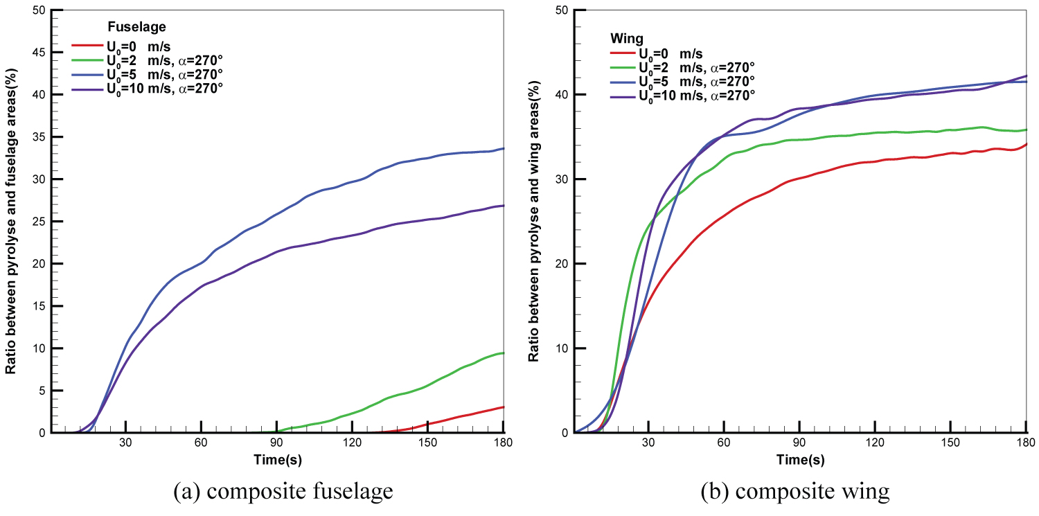
During fire propagation, a large amount of energy is released in the form of radiation, and as a result, the heat feedback from the gaseous flame increases the pyrolysis area of composite material. The ratio of the pyrolysis area to the fuselage one as well as to the wing area as a function of time for various wind speeds is presented in Figure 7. The ratio of the pyrolysis area to the fuselage one (cf. Figure 7a) is below 10% for a wind speed below 2 m/s. For a medium wind of 5 m/s, the ratio is considerably higher with a magnitude of 25% due to an impingement of the buoyant plume on the fuselage surface with an increase in the peak by a factor of 10 relative to quiescent fires. The high wind speed of 10 m/s leads to a shallower smoke plume, and a dramatic increase in the pyrolysis area over the fuselage is brought about with a ratio of about 35%. Over the wing skin (cf. Figure7a), an increase of wind speed from 2 to 10 m/s results in an increase in the ratio only by a factor of 10%. The ratio of the pyrolysis area to the wing surface reaches an asymptotic value of 40% for wind velocity above 5 m/s due to a flame cover over the composite surface (Figure 8). It is found that the peak in the ratio of the pyrolysis area to the wing surface for a wind speed below 2 m/s is almost equal in magnitude with a value of about 30%. Indeed, the simulation time of 180 seconds can't fully show evolution of the pyrolysis front especially for a wind speed below 2 m/s, but it is sufficient to guide the evacuation strategy.
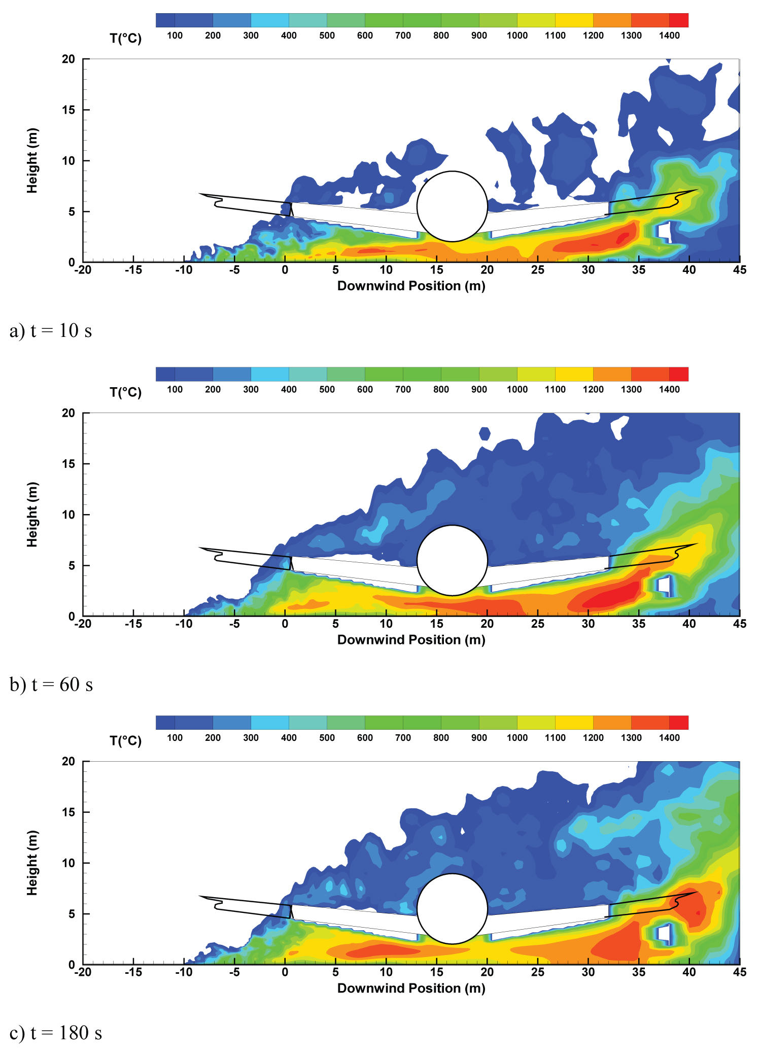
The instantaneous shape of the flame where the gas temperature is higher than 500 ℃, during fire propagation over the composite material surface for wind speed of 10 m/s is illustrated in Figure 9. During the initial phase at t=10s, surrounding the cone of fuel vapor is a zone of luminous persistent flame. Above this zone is a further combustion region, but here there is intermittency and obvious turbulence in the flaming. With an increase in height, there is the non-reacting buoyant plume, which is generally turbulent in nature and characterized by decreasing velocity and temperature. Starting from 60 s, with an increase in the pyrolysis area (cf. Figure 7), the aircraft is fully engulfed by luminous regions of efficient combustion appearing randomly in the outer surface of the fire according to the turbulent fluctuations in the fire plume. The availability of sufficient oxygen allows the pyrolysis gases to undergo gas-phase combustion rapidly with an increase in luminous flame region. Wake regions are formed around aircraft and at times, spiralling vortex flows are seen in the plume. Shear-stresses between hot combustion products and fresh air make the flow unstable and amplify oscillations near the fire base due to large eddy structures corresponding to hot gases puffs burning [31]. Coherent structures appear also surrounding the wing, and the flame presents a pronounced instability due to crosswind, following the experimental observation [8-11].
Burning rate over the composite fuselage and liquid fuel
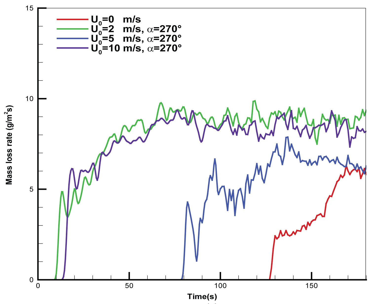
The magnitude of wind intensity brings about a significant change in the burning rate when the fire plume is displaced over the composite material surface due to a change in radiation distribution. This supports the postulation of an interaction between aircraft and fire that surrounds it. The surface burning corresponds to a signal representing the presence of flames above the region. A critical heat flux of 30 kW/m2 is needed, below which the mass loss rate of composite material enters rapidly the decay phase. History of the mean mass loss rate of the composite material per unit area averaged over the total pyrolysis surface is presented in Figure 10 at various wind speeds. It is seen that during the flame spread period, the mass loss rate increases quickly when an actively burning region over the surface of composite material is present, and is generally higher at strong wind velocity. An increase of wind speed from 2 to 5 m/s strengthens significantly degradation of the composite-type fuselage due to the enhanced impact of the flame on the fuselage skin. The resulting burning rate becomes tightly coupled to fire environment only at a medium wind speed of 5 m/s due to an impingement of the buoyant plume on the fuselage skin. At a high wind speed of 10 m/s, the magnitude of the burning rate in excess of 20 g/m2s exists due to a large flame base drag (cf. Figure 8e and Figure 8f). During the steady state period, the burning rate per unit area of composite material increases with a wind speed up to 2 m/s, beyond which it becomes largely independent of wind intensity. This dependence is related to the burning regime which becomes increasingly dominated by radiation as soot levels rise up to a value where the fire is effectively optically thick and saturated. For a wind speed below 2 m/s, the burning rate decreases to a magnitude of 8 g/m2s because the buoyancy-controlled flame stands up into a plume in front of aircraft; the burning of composite material occurs as a result of attachment of the actively combusting region only under the wing adjacent to the pool fire. For a wind velocity above 5 m/s, only 10 s is sufficient for starting degradation of the composite material. With a low wind speed of 2 m/s, about 80 s are required to starting degradation of such composite material.
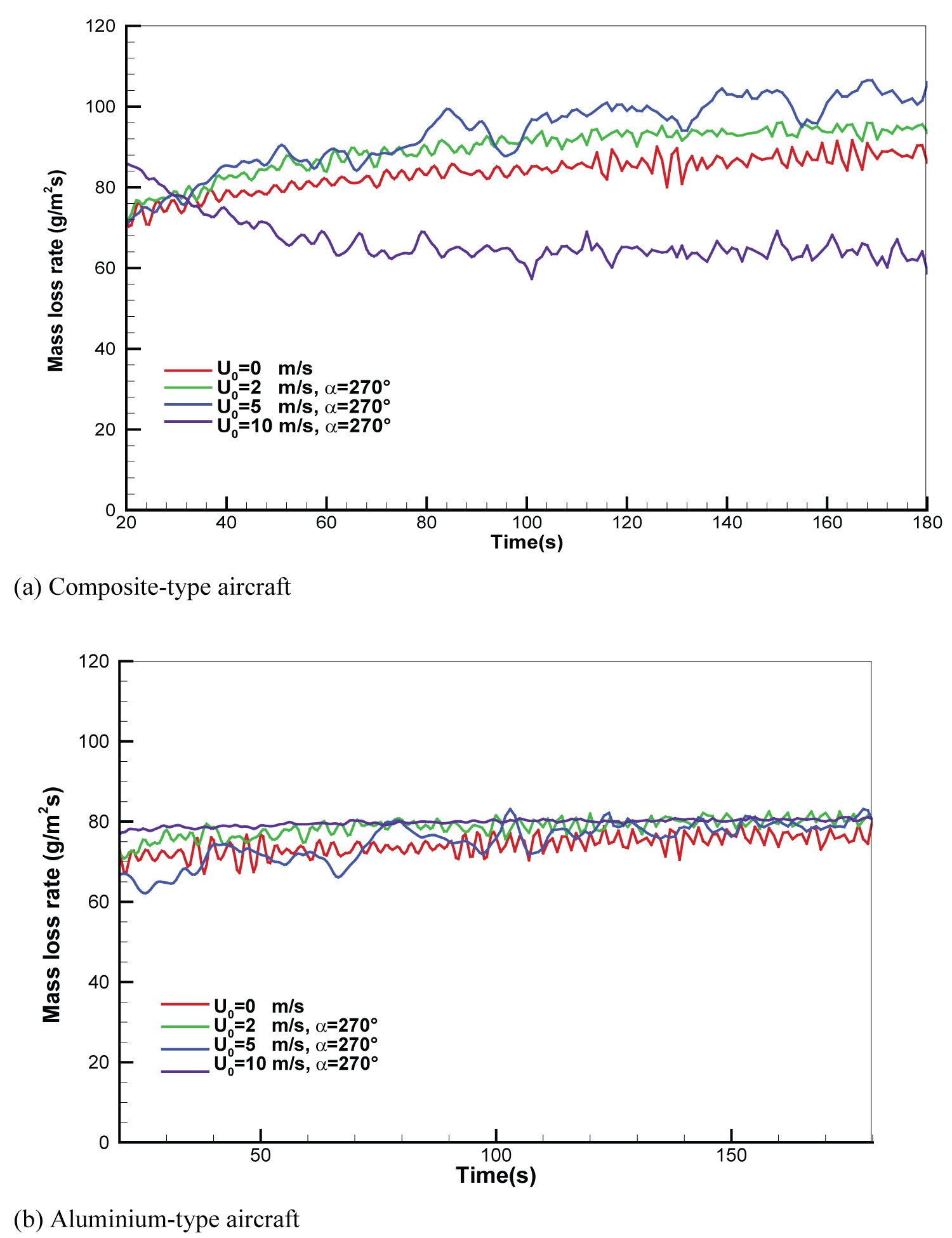
This analyses consider a liquid pool fire burning at steady-state after the initial stages of a fire during about 20 s. The heat feedback from the flame to the liquid pool surface affects directly the liquid heating rate to its boiling point of about 220 ℃ and consequently, its vaporization rate. History of the mass loss rate of liquid fuel at various wind intensities is presented in Figure 11. For a composite-type aircraft (cf. Figure 11a), the average regression rate is found to increase from about 80 g/m2s under a quiescent condition to 100 g/m2s with a rise of wind velocity to 5 m/s. This is attributed to the fact that a crosswind strengths the heat feedback from flame to liquid surface, and as a result, induces the most rapid regression of the liquid fuel. However, a further increase of wind speed to 10 m/s greatly attenuates radiation feedback to the liquid fuel surface due to reduction in the flame temperature beneath belly of composite-type fuselage (cf. Figure 8e), thereby depressing the mass burning rate. Besides, the oxygen under the fuselage is particularly low due to the accumulated fuel inside the gap due to pyrolysis of the composite material, resulting in a decrease of the mass transfer number B (cf. Eq.6), and consequently, of the regression rate (cf. Figure 11a). For an aluminium-type aircraft (cf. Figure 11b), the mass loss rate of the liquid fuel is about 80 g/m2s regardless of wind speed, which represents a decrease by a factor of about 30% in comparison with that for a composite-type aircraft at a medium speed of 5 m/s. The average fuel recession rate is in an order of about 6.5-7 mm/min as a function of wind speed, which follows closely the fuel recession rate measured during the course of the experiment in a large-scale liquid pool [34].
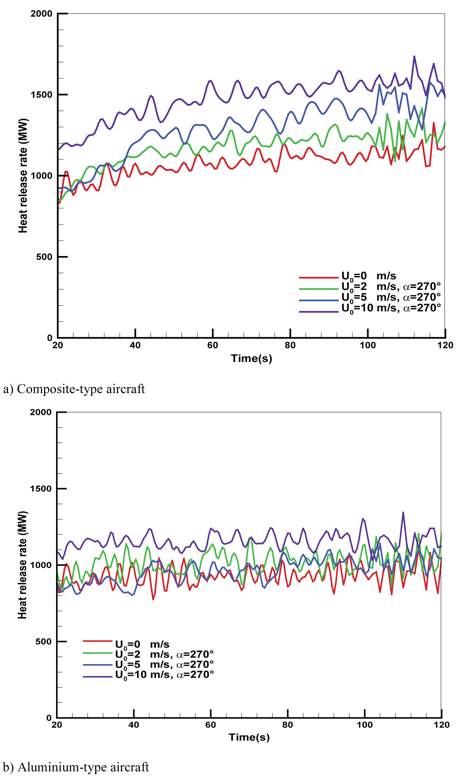
History of the heat release rate (HRR) generated from an aviation-fuel fire engulfing a full scale aluminium- or composite-type aircraft for different wind speeds is shown in Figure 12. Globally, the total supply of energy is elevated or depressed depending on the local air-to-fuel ratios and efficiency of mixing, affected by the wind conditions. Regardless of aircraft type, a high wind speed brings fuel to the outside pyrolysis zone where it can be combusted more efficiently due to large amount of oxygen, to release pluses of much more powerful energy from the flames. For the quiescent pool fire engulfing a composite-type aircraft (cf. Figure 8a), the buoyancy-induced air entrainment provides a mixing of fuel to air, and contribution of the pyrolysis gases from the composite material to the total heat generation is practically negligible in comparison with that from the liquid fuel, exhibiting the lowest HRR of about 1000 MW. A high wind speed above 5 m/s can alter the flame shape as well as pyrolysis zone over the fuselage and wing skins, and entrainment phenomena. When the wind-assisted fire propagation is fully developed over surface of the composite material, the heat release rate reaches its maximum value in a range of 1200 MW to 1500 MW with an increase of wind speed from 2 to 10 m/s due to a large contribution of the pyrolysis gases from the composite material over the fuselage and wing skins (cf. Figure 7a). For an aluminium-type aircraft (cf. Figure 8b), the heat release rate is closely correlated with the trend of the regression rate of liquid fuel (cf. Figure 11b). The heat release rate for a composite type aircraft becomes the more intensive in comparison with that for an aluminium-type one for a wind speed above 5 m/s. The fire power from a composite-type aircraft represents an increase of about 30% in comparison with that from an aluminium-type one when a wind speed increases to 5 m/s, mainly due to contribution of the pyrolysis gases from the composite material.
Time averaged thermal plume
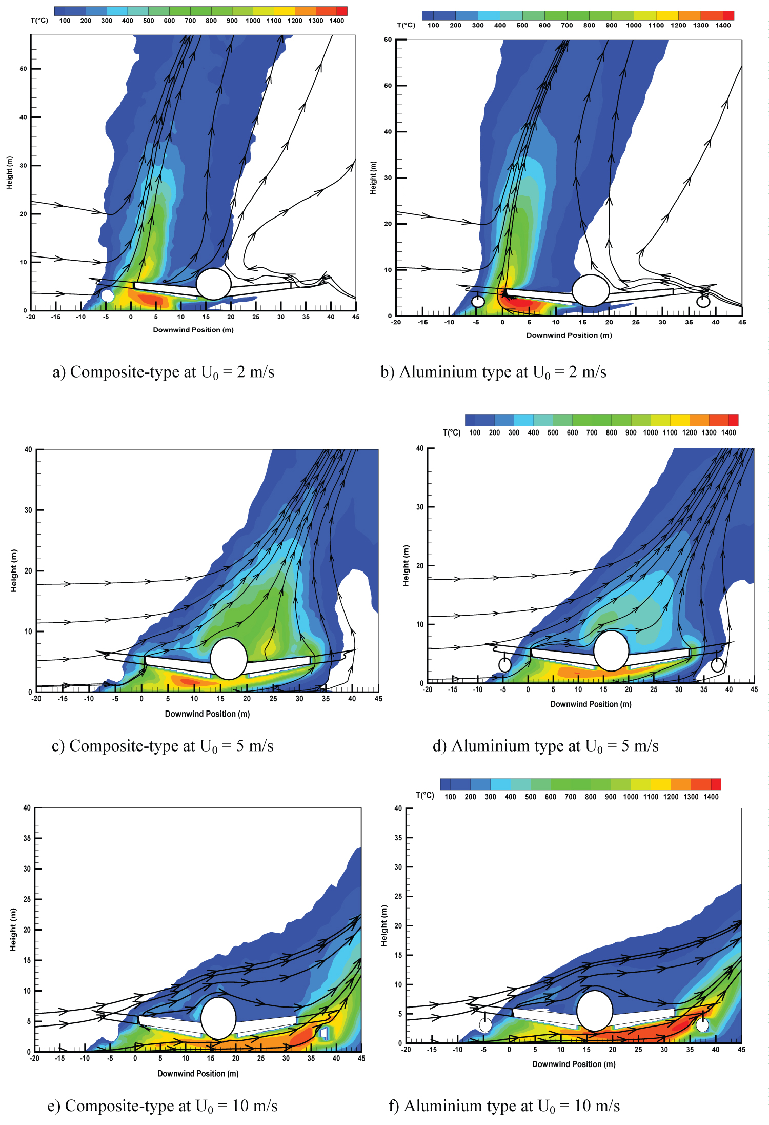
The time-averaged temperature field on a wind-assisted liquid pool fire engulfing an aluminium- or composite-type aircraft is presented in Figure 8. The time period over which the computation outputs were averaged from the last 60 seconds is considered as a quasi-steady period. Under a variety of wind conditions, the prediction suggests three main behaviors, consistent to the experimental observation [17].
1) At a low wind speed of 2 m/s (cf. Figure 8a and Figure 8b), the main part of the flame is practically insensitive to the material type of aircraft skin. The primary flame zone is essentially vertical and buoyancy dominated with a peak temperature of 1400 ℃, located near the fuel source and far away from the aircraft. Indeed, for a composite-type aircraft, there is an excess of fuel from degradation of the composite material over the wing skin, inducing an increase in the thermal plume volume with time during the fire growth stage. Note that under a quiescent condition, the main behaviors of the flame are rather similar to these observed for a low wind speed of 2 m/s because air entrainment flow velocity can be of the same order of magnitude of 2 m/s. A weak cross-flow is significantly deflected near the fire source as a result of an enhanced thermal blockage by the buoyancy forces. Nevertheless, the wind restricts the flow of entrained air and produces highly-mixed, and therefore highly combusting regions below the wing adjacent to the pool of the liquid fuel.
2) For a medium wind speed of 5 m/s (cf. Figure 8c and Figure 8d), the flame is elongated in the downstream direction, and the region directly surrounding just in front of the aircraft is immersed in a highly combusting zone with a peak temperature of 1300 ℃ due to complex wind/vorticity interactions. Flow is moving over the top of the aircraft creating streamwise vortices while fuel-rich air is forced below the fuselage. On the upper leeward side of the aircraft, the presence of a composite-type aircraft induces an increase of the flame cover with a temperature level of about 700 ℃ instead of approximately 500 ℃ for an aluminium type one. Moreover, on the leeward side of the composite-type aircraft, the enhanced convective transport, as a whole, leads to a significant amplitude of temperature with a peak value of 1300 ℃. The length of flame base drag (T > 500 ℃) is approximately two time the pool size with this wind speed regardless of aircraft type.
3) A high wind speed of 10 m/s enhances the interaction between cross-flow and aircraft, and consequently, facilitates the global flame shape alterations (cf. Figure 8e and Figure 8f). Such situation is combined with global enhancements in turbulent mixing by the presence of the vortices in the wake behind the aircraft. The magnitude of wind speed is sufficient to direct the flame to the bottom surface of the fuselage, causing an excess of the pyrolysis gases there from the composite-type fuselage. For the composite-type aircraft, oxygen beneath belly of fuselage is probably insufficient to consume the fuel gas accumulated inside the gap, and the combustion within a vitiated gap is close to rich limit of flammability. Consequently, the presence of a composite-type aircraft (cf. Figure 8e) instead of an aluminium type one (cf. Figure 8f) results in a flame temperature of about 1200 ℃ instead of approximately 1400 ℃ for an aluminium type one, i.e. a reduction in temperature of about 200 ℃ beneath belly of fuselage. Regardless of the aircraft type, the length of visible flame (T > 500 ℃) base drag is up to 3.5 times the pool size in presence of a strong wind.
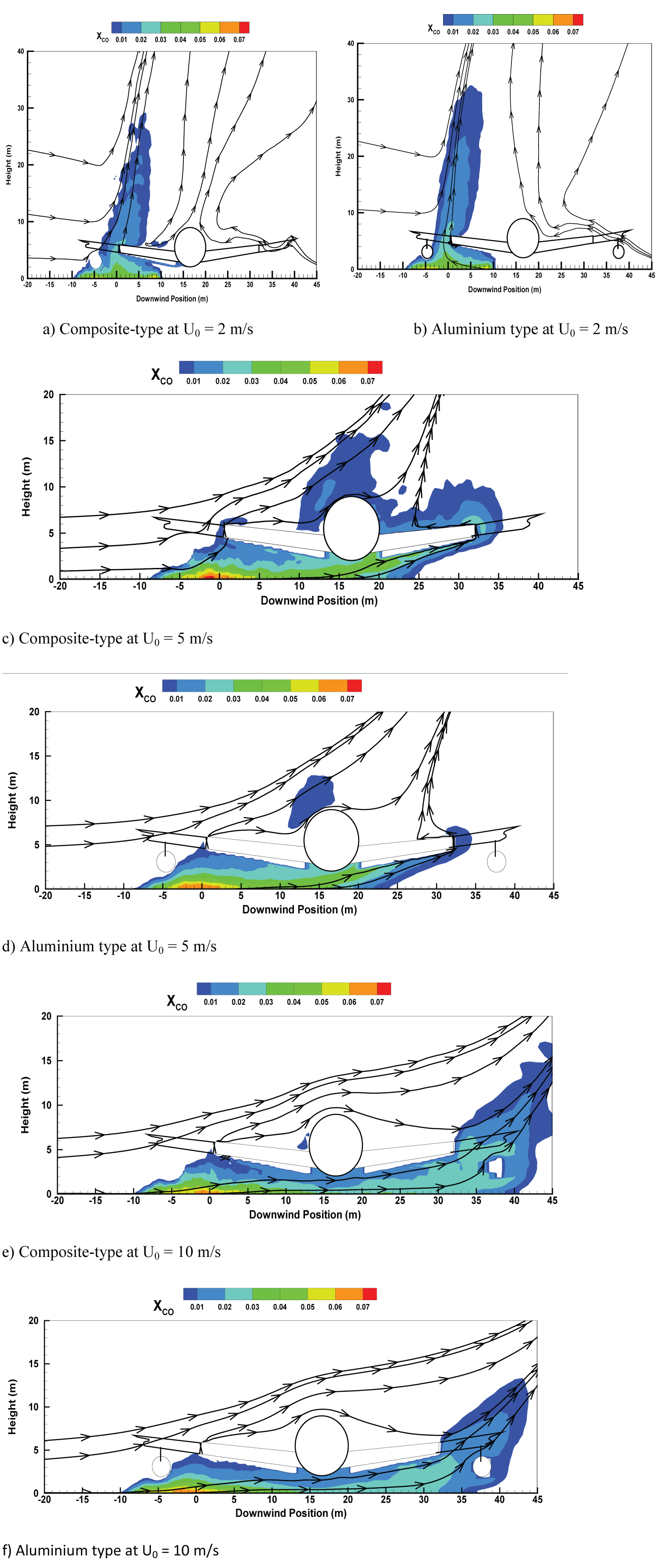
The time-averaged CO molar fraction on a wind-assisted liquid fire engulfing an aircraft at various wind speeds is presented in Figure 13. Obviously, a low wind speed of 2 m/s (cf. Figure 13a and Figure 13b) is insufficient to direct the smoke towards the fuselage, and only the vertical primary flame zone contains large CO with a peak value of 5% regardless of aircraft type. For a medium wind speed of 5 m/s (cf. Figure 13c and Figure 13d), aircraft is immersed within the flame with a remarkable CO production over the top of the aircraft. In comparison with the aluminium-type aircraft, the composite-type aircraft in fire change slightly the distribution of the toxic product as CO with a difference 2% in the peak value on the upper leeward side of the fuselage. At a high wind speed of 10 m/s (cf. Figure 13e and Figure 13f), the smoke is ejected from underneath of aircraft, and this creates a second large smoke zone with a peak in toxic product as CO of 3% behind the fuselage. Nevertheless, on the leeward side of the composite-type aircraft, the enhanced convective transport, as a whole, leads to a larger smoke zone with a significant amplitude of CO molar fraction of 3%. A windward flow at U0 = 10 m/s is strongly accelerated over the top of the aircraft, allowing to the suppression of smoke there thanks to an increased convective transport.
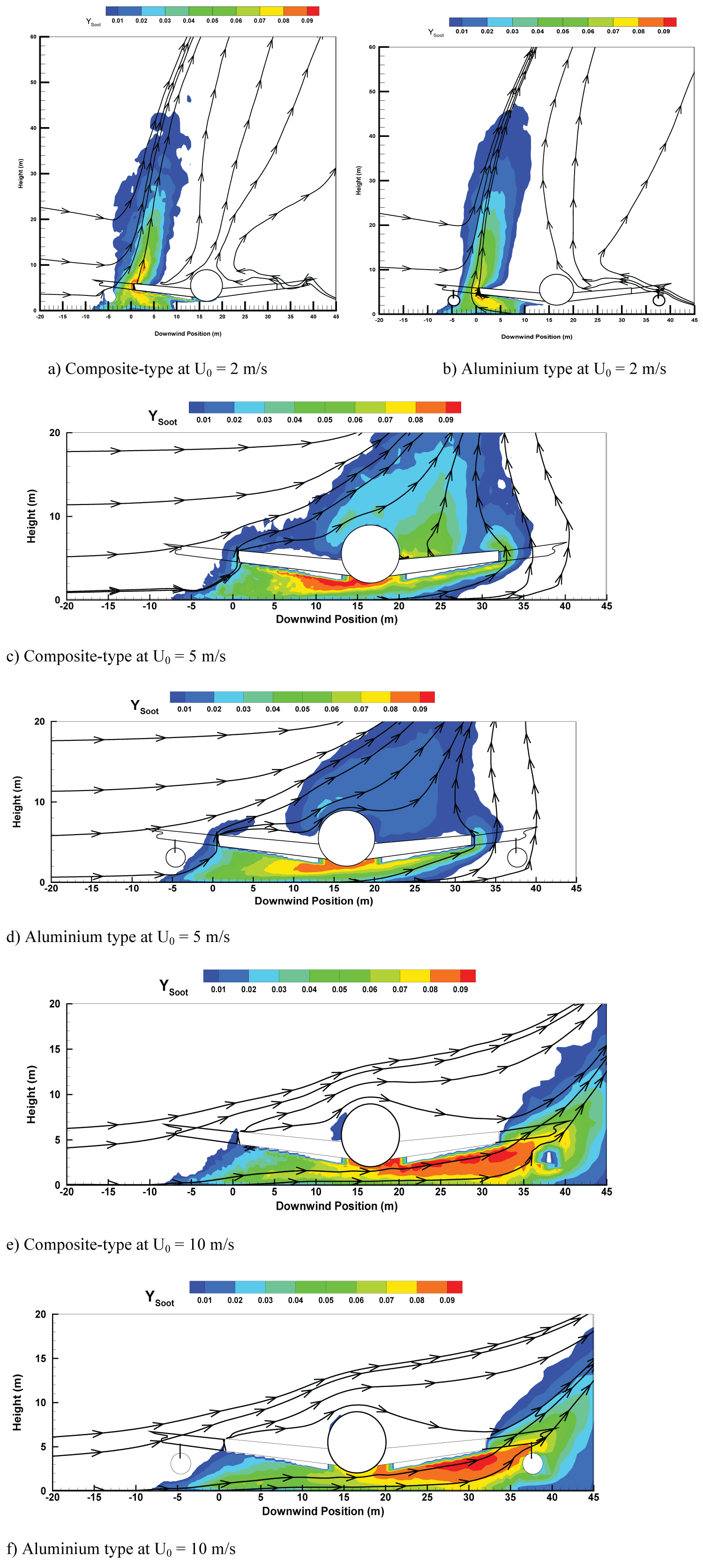
It is desirable to know soot levels in a wind-assisted liquid fire engulfing an aircraft as it reduces visibility, enhances radiation flux and causes soot environmental pollution [35]. The time-averaged soot mass fraction is illustrated at various wind speeds in Figure 14. Note that soot formation is usually conjugated with CO production with a similar behavior between them. At a low wind speed of 2 m/s, the smoke containing large soot appears only in the primary flame zone far away from the fuselage (cf. Figure 14a and Figure 14b) in spite of aircraft type. Note that presence of a composite-type aircraft in fire change significantly the distribution of toxic product as soot only for a medium wind speed of 5 m/s (cf. Figure 14c and Figure 14d). It is found that the composite-type aircraft at U0 = 5 m/s induces an increase of soot production by a factor of 20% on the upper leeward side of the aircraft in comparison with an aluminium-type one. At a high wind speed of 10 m/s (cf. Figure 14e and Figure 14f), regardless of aircraft type, a large soot production with a peak value of 5% occurs beneath belly of fuselage via the ejected flame.
Conclusions
A numerical study was conducted to supply information about the thermal exposure of a composite-type aircraft immersed in a fire environment. Heat flux and temperature fields have been studied in a variety of ways and the largest factor affecting the thermal environment is identified as wind conditions. The CFD approach seems much more realistic, when dealing with the characteristics of the wind-induced interaction of fires and large objects as aircraft, than the simpler alternatives regarding the temperature field and toxic products. The importance of considering the presence of an aircraft in fire is due to the coupling that occurs between the object size, shape, location, orientation and the fire environment.
Influence of the wind speed and the positioning of an aircraft in luminous flames on the heat flux to the fuselage skin is analysed. The peak in heat flux to the composite fuselage skin ranges from 50-240 kW/m2 as a function of the wind conditions, and contribution of the radiation is higher than 95% of the total heat flux. The peak in heat flux to a medium or high wind is about a factor of 4 increases of that to a low wind speed. As a consequence, the fire spread assisted by a strong wind is the most devastating mode of propagation in particular with a substitution of aluminium-type fuselage by flammable composite material. For a composite-type aircraft, ratio of the pyrolysis area to the fuselage skin area reaches to a value of about 30%, accompanied by a more important thermal plume. As a result, the fire power from a composite-type aircraft represents an increase of about 30% in comparison with that from aluminium-type one when a wind speed increases to 5 m/s. Transition from the unsteady to the steady mode occurs earlier at wind velocity above 5 m/s due to the flame impingement on the fuselage. The flame spread rate over a composite material surface is amplified with an increase in wind speed from 2 to 5 m/s. Increasing the wind intensity leads to a shallower smoke plume, but does not help to suppress soot and CO around the engulfed aircraft. The difference in the peak of the toxic products as CO/soot between an aluminium- and a composite-type aircraft in fire is below 2%.
The wind deviations in speed and direction are erratic in nature and contribute to the large spatial and temporal variations of the flame shape and heat flux in a real aircraft fire situation. A negligence of the unavoidable deviations of wind speed/direction from their average values in the numerical simulation may induce large difference from the real aircraft fire. More comprehensive pyrolysis model in addition to evaporation, charring and internal heating of composite material should be further investigated. Measurements of temperature, heat flux and toxic products from a real aircraft fire test would consolidate the insight provided by the CFD activity.
Acknowledgements
This study is sponsored by the European Project AirCraft-Fire under Contract number FP7-2010-265612-CP.
References
- ER Galea, NC Markatos (1987) A review of mathematical modelling of aircraft cabin fires. Appl Math Modelling 11: 162-171.
- (2006) Uncontained engine failure, Boeing 737-236 series 1, G-BGJL. Aircraft Accident Investigation Board (AAIB), United Kingdom.
- Markstein GH (1976) Radiative energy transfer from turbulent diffusion flames. Combustion and Flmae 27: 51-63.
- Fateh T, Zhang J, Delichatsios M, et al. (2017) Experimental investigation and numerical modelling of the fire performance for epoxy resin carbon fibre composites of variable thicknesses. Fire and Materials 41: 307-322.
- Fateh T, Kahanji C, Joseph P, et al. (2017) A study of the effect of thickness on the thermal degradation and flammability characteristics of some composite materials using a cone calorimeter. Journal of Fire Sciences 35: 547-564.
- M Lavid, AL Berlad (1976) Gravitational effects on chemically reacting boundary layer flows over a horizontal flat plate. Sixteenth Symposium (International) on Combustion. The Combustion Institute, Pittsburgh, 1157-1167.
- AA Putnam (1963) A model study of wind-blown free burning fires. Tenth Symposium (International) on Combustion. The Combustion Institute, Pittsburgh, 1039-1046.
- Longhua Hu, Junjun Hu, Shuai Liu, et al. (2015) Evolution of heat feedback in medium pool fires with cross air flow and scaling of mass burning flux by a stagnant layer theory solution. Proc Combust Inst 35: 2511-2518.
- W Tang, D Gorham, M Gollner, et al. (2015) Forward pulsation behaviour of wind-driven line fires. 9th U.S. Natl Combust Meet.
- Wei Tang, Colin Miller, Michael Gollner (2017) Local flame attachment and heat fluxes in wind-driven line fires. Proc Combust Inst 36: 3253-3261.
- Yasushi Oka (2002) Effects of cross-winds to apparent flame height and tilt angle from several kinds of fire source. Fire Saf Sci 7: 915-926.
- LH Russell, JA Cannfield (1973) Experimental measurement of heat transfer to a cylinder immersed in a large aviation-fuel fire, Journal of Heat Transfer 95C: 397-407.
- J Gregory, NR Keltner, R Mata (1989) Thermal measurements in large pool fires. Journal of Heat Transfer 111: 446-454.
- Birk AM, Oosthuizen PH (1982) Model for the prediction of radiant heat transfer to a horizontal cylinder engulfed in flames, ASME paper No.82-WA/HT-52.
- LA Gritzo, VF Nicolette (1997) Coupling of large fire phenomenon with object geometry and object thermal response. Journal of Fire Sciences 15: 427-442.
- NR Keltner, W Gill, LA Kent (1994) Simulating fuel spill fires under the wing of an aircraft. Fire Safety Science, Proceedings of the 4th International Symposium, Canada, 1017-1028.
- JM Suo-Anttila, L Gritzo (2011) The effects of wind on fire environments containing large cylinders, Combustion Science and Technology 181: 68-77.
- YL Sinai, MP Owens (1995) Validation of CFD modelling of unconfined pool fires with cross-wind: Flame geometry. Fire Safety J 24: 1-34.
- Ugurlu Ö (2016) Analysis of fire and explosion accidents occurring in tankers transporting hazardous cargoes. International Journal of Industrial Ergonomics 55: 1-11.
- Sarialioglu S, Ugurlu Ö, Aydin M, et al. (2020) A hybrid model for human-factor analysis of engine-room fires on ships: HFACS-PV&FFTA. Ocean Engineering, 217, 107992, Journal of Industrial Ergonomics 55: 1-11.
- Wang L, Wang J, Shi M, et al. (2020) Critical risk factors in ship fire accidents. Maritime Policy & Management 1-19.
- You J, Chung YJ (2015) Study on the ship fire analysis according to explosion hazard. Fire Science and Engineering 29: 80-86.
- Gottuk DT, Rohy RJ, Beyler CI (1992) Study of carbon monoxide and smoke yields from compartment fires with external burning. 24th Symposium (international) on Combustion, The Combustion Institute, Pittsburgh, 1729-1735.
- K Mcgrattan, R Mcdermott, S Hostikka, et al. (2013) Fire dynamics simulator user's guide. NIST Special Publication.
- GD Wang, HY Wang, JM Most (2013) Mathematical modelling of the interaction between wind and aviation-fuel fire engulfing a fuselage-sized cylinder. Journal of Fire Sciences 31: 424-448.
- Chen ZB, Wen JX, Xu BP, et al. (2011) The extension of eddy dissipation concept in the framework of large eddy simulation and the subsequent modification. 23rd ICDERS, Irvine, USA.
- T Beji, J Zhang, Delichatsios MA (2008) Determination of soot formation rate from laminar smoke point measurements. Comb Sci and Tech 180: 927-940.
- K Himoto, T Tanaka (2004) A burning model for charring materials and its application to the compartment fire development. Fire Science and Technology 23: 170-190.
- C Lautenberger, C Fernandez-Pello (2009) Generalized pyrolysis model for combustible solids. Fire Safety Journal 44: 819-839.
- Murty Kanury (1984) Introduction to combustion phenomena. Gordon, New York.
- G Kolb, JL Torero, JM Most, et al. (1997) Cross flow effects on the flame height of an intermediate scale diffusion flame. Proceedings of the International Symposium on Fire and Technology, Seoul, Korea, 169-177.
- JL Consalvi, Y Pizzo, B Porterie (2008) Numerical analysis of the heating process in upward flame spread over thick PMMA slabs. Fire Safety Journal 43: 351-362.
- Lois E, J Swithenbank (1979) Fire hazards in oil tank arrays in a wind, Proc 17th Symp. (Int.) on Combustion, Leeds, Combust. Inst, Pittsburgh, PA.
- L Orloff, J de Ris, MA Delichatsios (1987) Chemical effects on molecular species concentrations in turbulent fires. Combustion and Flame 69: 273-289.
Corresponding Author
HY Wang, Institut P', Fluides-Thermique-Combustion, CNRS, ENSMA, Université de Poitiers, BP 40109, F86961 Futuroscope Chasseneuil Cedex, France.
Copyright
© 2020 Wang HY, et al. This is an open-access article distributed under the terms of the Creative Commons Attribution License, which permits unrestricted use, distribution, and reproduction in any medium, provided the original author and source are credited.