Mass Loss of a Polymeric Composite under Action of Space Radiations
Abstract
The effect of electron, proton and electromagnetic radiations on mass loss of EKOM-1 polymeric composite was studied. Irradiation was made by 40-keV electrons and protons and electromagnetic radiation in vacuum chamber of the "UV-1/2" test facility. It was found that parameters characterizing the synergistic effects of mass loss of the material for stated conditions of electron-proton and combined radiations are the functions of irradiation time. To interpret the experimental data, a physical-mathematical model of mass loss of polymeric materials in vacuum was proposed. The obtained data can be explained by diffusion fluxes associated with the gradient of concentration of radiolysis products and increase of gas permeability of a material under radiation.
Keywords
Space radiations, Composite, Thermal control coating, Mass loss, Volatile products
Introduction
Polymeric materials find ever-widening applications in space technique. This is tied with the simplicity of producing the polymeric-based composites with the predetermined set of properties. However, these materials in space become the sources of volatile products (VP) that increase density of spacecraft outer atmosphere that undermines the serviceability of the on-board equipment [1-5]. Therefore, studying the mass loss of spacecraft materials in service conditions is a vital task. For example, action of electron, proton and electromagnetic radiations on external coatings of high-elliptical and high-altitude satellites can result in noticeable growth of their mass loss. But, if actions of individual radiations on mass loss of materials in vacuum are already known in some aspects [6-11], the information on how they act in various combinations and as a whole is almost absent.
This work is devoted to studying action of separate (electron, proton, and electromagnetic), paired, and total set of radiations on mass loss of a pattern material in vacuum. The primary focus was on studying and interpretation of synergistic effects appearing in the course of mass loss of the pattern material EKOM-1 polymeric composite, the widely used spacecraft thermal control coating being a composition of acrylic copolymer and powdered zinc oxide (ZnO).
Experimental Technique
To carry out the experiments, EKOM-1 thermal control coating (TCC) with a glass transition temperature of about 390 K was chosen as a model material. The EKOM-1 is a composite consisting of a polymeric matrix (acrylic copolymer) and a filler (ZnO particles). Weight ratio of the matrix and the filler is 1:5.5. No electrostatic discharges occur when irradiating the EKOM-1 because its specific resistance does not exceed 5 × 10⁵ Ohm/m. The 100-μm thick coating was applied to the substrate made of AMg6 aluminum alloy with dia. 30 mm. This sample was clamped to the metal table that prevents charging.
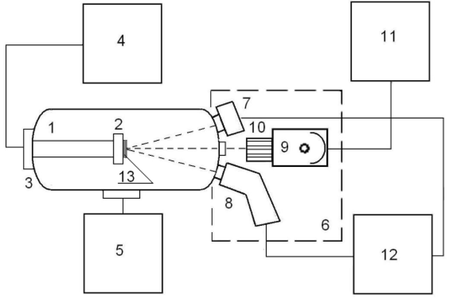
Effect of radiation on mass loss of the model material was determined in two stages. At the first stage, the samples were irradiated in the vacuum chamber of the "UV-1/2" test facility (Figure 1). Together with the samples to be irradiated, the witness samples protected from radiation were also fastened to the table of the "UV-1/2". Before and after irradiation the both types of samples were weighed using the AUW-220D Shimadzu microbalances (accuracy is ± 10-5 g).
The samples were irradiated under the following conditions:
• Pressure in the chamber 10-4 Pa;
• Temperature of the table with samples was 30 ± 1 ℃;
• Electron and proton flux densities (φe and φp) were 5 × 10¹⁴ m-2s-1;
• Electron and proton fluxes were altered from 1018 to 5 × 10²⁰ m-2;
• UV irradiance was equal to 1 ESR (equivalence of solar radiation);
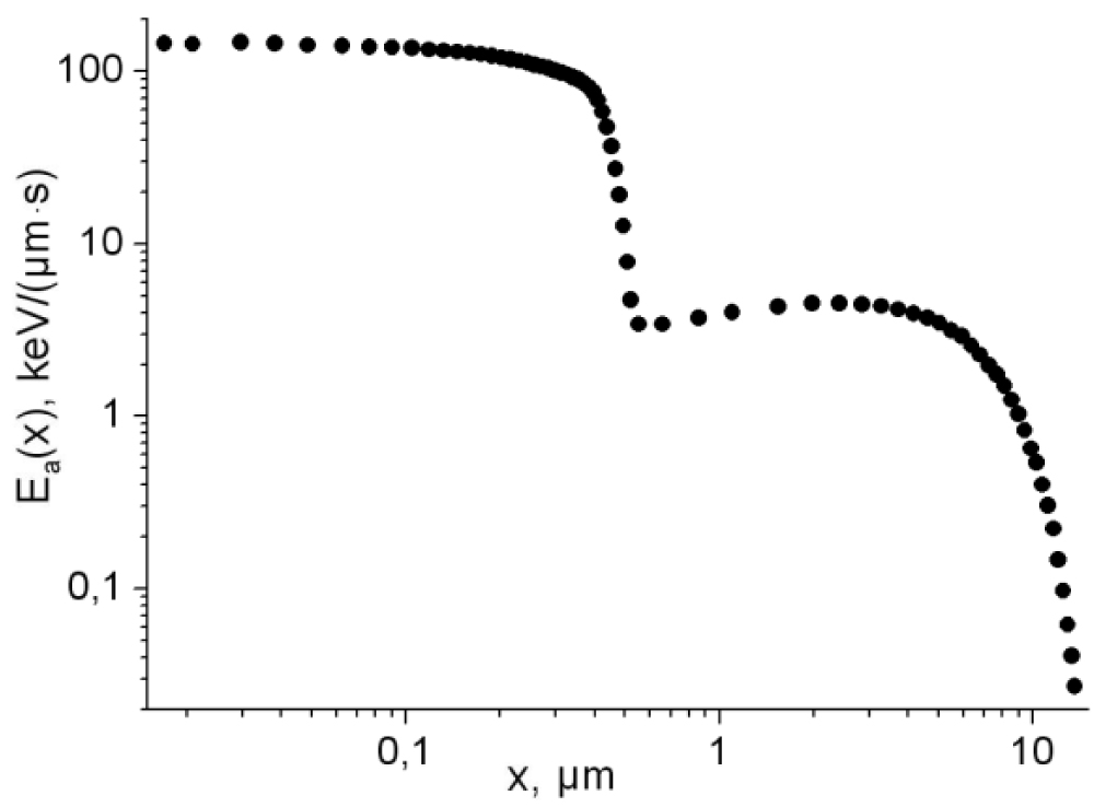
Electron (Ее) and proton (Ер) energies were 40 keV. These energies are characteristic for magnetospheric plasma at GSO. The purpose of the work is not an exact reproduction of radiation conditions in GEO but making a comparative analysis of mass losses of TCC being irradiated by electrons and protons of equal energies. It is obvious that major contribution to the near-surface absorbed dose of TCC make electrons and protons below 40 keV.
However, the path length of protons having lesser energies is less than 0.8 μm. This fact impedes an analysis of experimental results therefore we chose energy of 40 keV (Figure 2).
Each experiment was conducted with a batch of three or five samples. In the chapter, "Results and discussion", the average values of mass loss for three samples are presented.
Mathematical Model
The mathematical model is based on the assumption that mass loss of a polymeric composite embraces, in general, the following processes [11]:
• Desorption of VP adsorbed on material surface and/or formed on it under radiations;
• Diffusion and desorption of products absorbed or formed in material due to thermal decomposition and radiation;
• Sublimation of material in vacuum under radiations.
The model also postulates that Mi(t) - mass loss rate for i-type VP is proportional to its concentration in the near-surface layer of material Ci(l - νt,t).
Where mi - mass of i-type molecule, g; ν - sublimation rate of material, μm/s; t - current time, s; l - material thickness, μm; ki (t) - effective desorption coefficient of i-type VP, μm/s.
Total mass loss from the unit surface of material Mtotal(t) by time t can be calculated as follows:
Where N - number of types of VP in irradiated material.
Total mass of VP in a sample before radiation can be calculated
Where A - surface area of sample; Ri - concentration of i-type VP in material at the initial moment; K - number of types of VP in non-radiated material.
Thus, to find mass loss caused by i-type VP one need to know its concentration in the near-surface layer of material. Typical thickness of TCC is about 100 μm which is many times less as compared with other linear sizes of samples. Therefore, accounting for the made assumptions the task on mass loss caused by i-type VP under radiation in vacuum is coming to solving the one-dimensional boundary value problem:
In this paper, composites with preset levels of mass loss were being modeled using the one-dimensional equations describing migration of potential out gassing products in heterogeneous materials. The coordinate-dependent diffusion equation that was used to analyze numerically distribution of radiolysis products in a composite:
Where Ci(x,t) - concentration of i-type VP in material; χi - chemical reaction rate with involvement of i-type VP, s-1; Di(x,t) - effective diffusion coefficient of i-type VP, μm2/s; Ri(x) - concentration of i-type VP in material at the initial moment; Si(x) - function of i-type VP source dependent on type of material, spectrum, content and intensity of radiation.
The source function Si(x), in its shape, repeats distribution of absorbed radiation energy in polymeric matrix of model material. Figure 3 shows distributions of absorbed energy of 40-keV electrons and protons obtained when solving the radiation transport problem by the Monte-Carlo method.
Irregularity of permeability over material thickness was taken into account by inserting the diffusion coefficient that increases with time
Where Di0 - effective diffusion coefficient of i-type VP before radiation; αi(x) ≥ 0 - weight function proportional to φ.Eα(x) which represents distribution of absorbed energy rate in polymeric matrix under radiation with flux density φ; T - irradiation time.
Numerical calculations quantitatively reproducing experiments were also made in two stages. The first one was dedicated to solving the set (3)-(6) that describes changes of VP concentration in material under radiation. It has been considered that VP in material before radiation was distributed uniformly.
The non-linear regression analysis methods [12,13] and the discrepancy minimization techniques were used for processing the data obtained at the second stage of experiment to precise the mathematical model parameters (1)-(8).
Results and Discussion
In all experiments, the irradiation conditions were the following: φe = φp = 5 × 10¹⁴ m-2s-1 and 1 ESR. Corresponding results are given in Figure 3 and Figure 4. There were three series of experiments in which mass loss of samples under separate irradiations and their various combinations on irradiation time were studied.
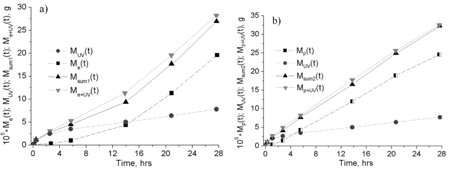
• The first series: Irradiation by electrons Me(t) (Figure 3a), protons Mp(t) (Figure 3b), UV MUV(t) (Figure 3);
• The second series: Simultaneous action of electrons and UV Me+UV(t) (Figure 3a), protons and UV Mp+UV(t) (Figure 3b), electrons and protons Me+p(t) (Figure 4);
• The third series: Simultaneous action of electrons, protons and UV Me+p+UV(t) (Figure 4).
The irradiation conditions were the following: φe = φp = 5 × 10¹⁴ m-2s-1 and 1 ESR. Figure 3 shows the experimental data. The results shown here and below were found by subtracting mass loss of the reference sample M0(t) from total mass loss of a sample at proper exposure, i.e. calculated, for example, from formulae:
Where Mtotal e(t), Mtotal p(t) и Mtotal UV(t) - total mass losses of samples irradiated by electrons, protons or UV respectively; M0(t) - mass loss of the reference sample.
Thus Me(t), Mp(t) and MUV(t) are the mass losses of the samples due to irradiation. Having analyzed the dependencies, one can see that mass loss rate becomes almost constant very quickly under proton irradiation and increases throughout the observation period in the case of electron irradiation. It should be noted that Mp(t) > Me(t) throughout the experiment if radiation conditions are equal. For example, mass losses of electron and proton-irradiated samples at t = 28 hrs (it corresponds to the fluence of 5 × 10¹⁹ m-2) are 18 × 10-5 and 26 × 10-5 g respectively. Having analyzed the dependencies, one can see that mass loss rate becomes almost constant very quickly under proton irradiation and increases throughout the observation period in the case of electron irradiation. It is followed from Figure 3 that mass loss of the sample under UV at t = 28 hrs is less than under electron (3a) and proton irradiation (3b) by 2.6 and 3.2 times respectively.
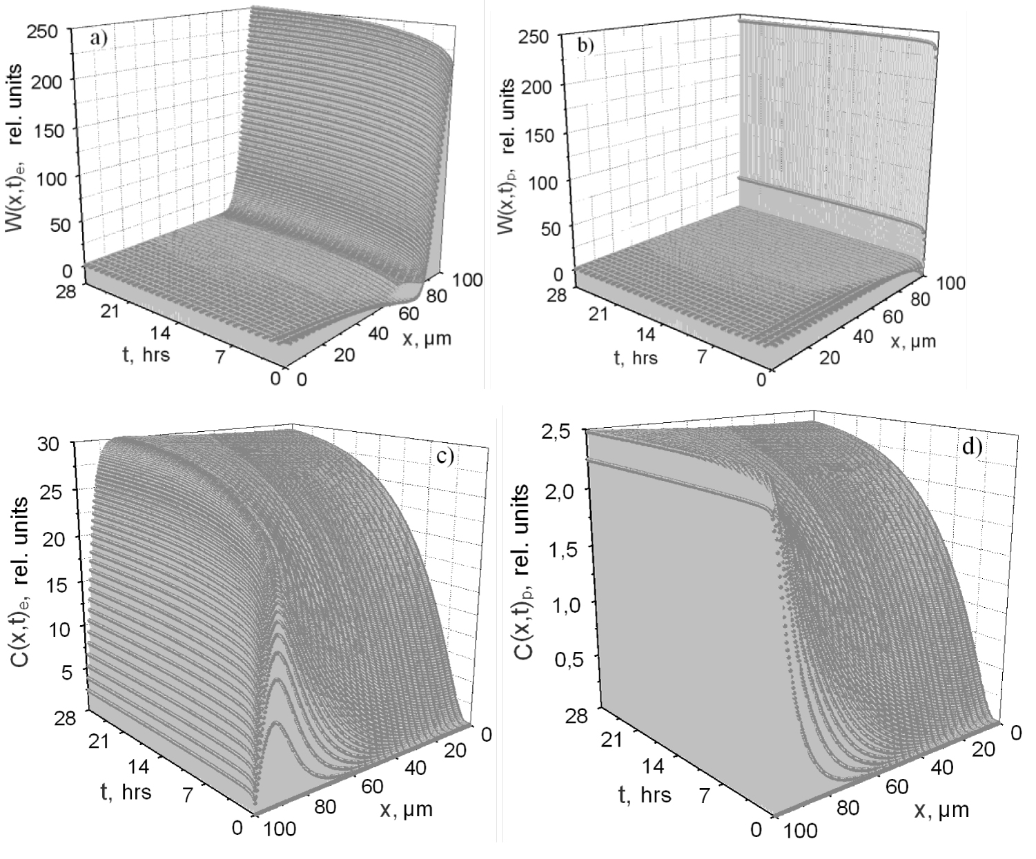
The results are explained by the fact that path lengths of 40-keV protons (0.6 μm) are much shorter than 40-keV electrons (16 μm). Therefore, the radiolysis products under the proton radiation are formed in a thinner near-surface layer of material, gas permeability of the layer growing in parallel with the absorbed dose causing the products to evolve in vacuum quicker as compared with the electron radiation. To illustrate the said, Figure 5 shows calculations of spatiotemporal distributions of diffusion flows We(x,t) (5a) and Wp(x,t) (5b)
And concentrations (5c,5d) Ce(x,t), Cp(x,t) of carbon dioxide being one of the important radiolysis products under the electron and proton radiations.
Comparing the results in Figure 5 one can see that W(x,t) in the layer that is being irradiated by electrons increases throughout the observation period and levels off quickly in the case of proton irradiation. It means that the amount of CO2 formed in material differs from the amount of CO2 evolved out in unit time only by the amount of CO2 diffusing towards the substrate. In the case of electron irradiation, a substantial accumulation of the radiolysis products takes place (5c) in contrast with the proton irradiation. This conclusion is confirmed by experimental data (Figure 3) and calculation data of mass loss rate under irradiation.
The second series of experiments was devoted to studying the mass loss of the sample under simultaneous action of electrons and protons. Here, the fluencies and flux densities were the same as in the previous series.
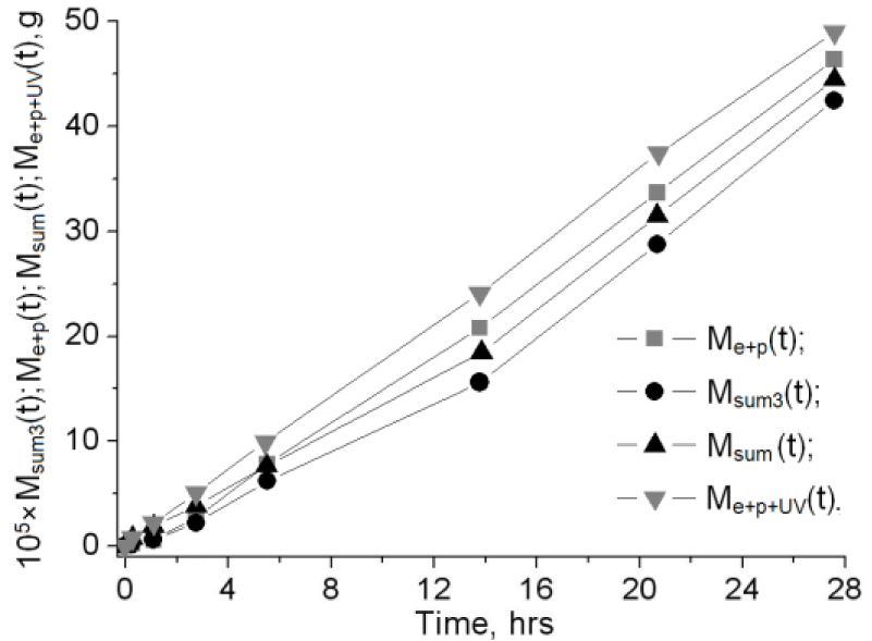
Figure 4 shows dependencies of mass loss on irradiation time for electron-proton Me+p(t) and combined action Me+p+UV(t) as well as the values of the functions Msum3(t) = Me(t) + Mp(t), Msum(t) = Me(t) + Mp(t) + MUV(t) being the sum of mass losses in the first series of experiments.
When comparing functions in Figure 4, one can see that maximum excess of Me+p(t) over Msum3(t) is 32% at total fluence of particles φe+p = 5 × 10¹⁹ m-2 and decreases down to 17% and 6% with the rise of φe+p to 7.5 × 10¹⁹ m-2 and 1020 m-2 respectively. These data can be interpreted in assumption that combined irradiation increases permeability of material more than separate irradiations alone. Maximum effect of this on transfer of radiolysis products in material is revealed at φe+p = 5 × 10¹⁹ m-2.
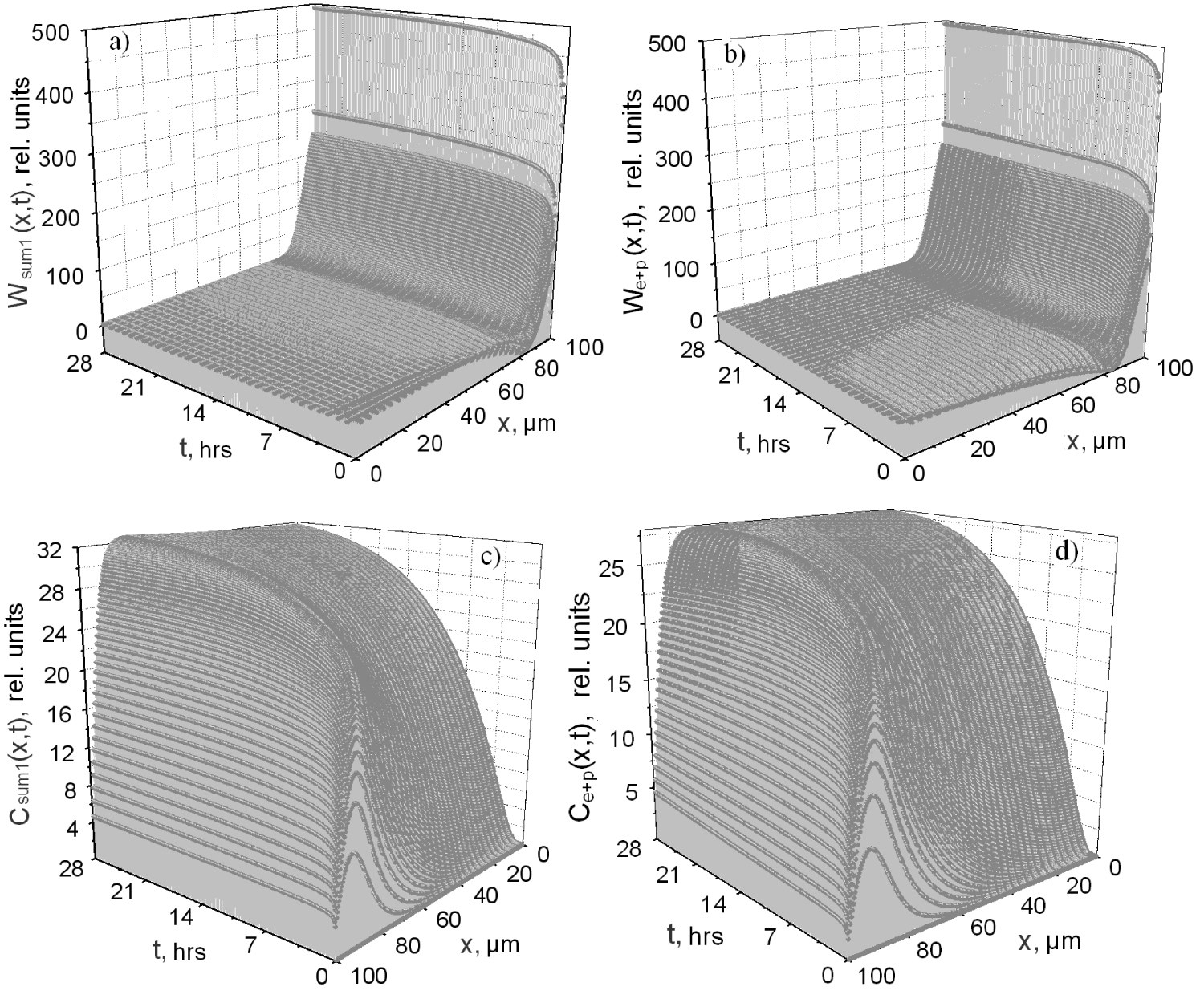
To visualize the said above, Figure 6 shows the calculation data. Here one can see that diffusion flow for the combined irradiation We+p(x,t) (Figure 6b) quickly overcomes the summarized flow Wsum1(x,t) = We(x,t) + Wp(x,t) (Figure 6a) and СО2 concentration in the material by the end of electron-proton irradiation Ce+p(x,t) (Figure 6d) is less than Csum1(x,t) = Ce(x,t) + Cp(x,t) (Figure 6c).
Diffusive constraining of radiolysis products at initial moment of irradiation leads to their accumulation in material. However, further irradiation causes the permeability of material to increase to such extent when not only major part of volatile products evolves from it but also the products accumulated earlier. Starting from a certain moment, there sets a balance when quantity of radiolysis products forming in a sample becomes almost equal to the quantity of the products leaving it except for the ones entering the chemical reactions, i.e. mass loss rate does not change.
To make a quantitative estimation of synergistic effects when analyzing experimental data, we introduce the following time-dependent non-dimensional parameters.
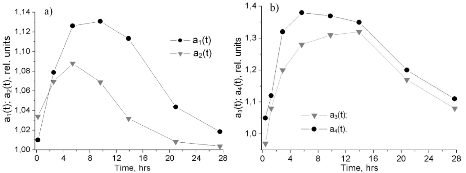
Their behavior is shown in Figure 7.
It is seen from Figure 7a that a1(t) < a2(t) at initial irradiation period. It is related to the fact that the radiolysis products are mostly formed far away from the surface as compared with the proton irradiation. Hence, in this case there is a time delay in their accumulation and making a contribution in mass loss.
One can see from Figure 7b that significant differences in functions a4(t) and a3(t) are observed only when t ≤ 14 hrs; later their behaviors coincide and a4(t) - a3(t) does not exceed 0.03. The fact that a3(t) = 0.93 at t = 1 hr is explained by the fact that radiolysis products forming under electron action in х < 99.4 μm do not contribute in total mass loss because the resultant flow in this area is directed towards the substrate (see Figure 6b). Value of a3(t) excesses 1 with the rise of fluence, growth of accumulated products and permeability of the material.
The contribution of UV in mass loss of material is quite likely to be tied with additional warming-up and activation of migration processes within the layer under irradiation. This, in turn, stimulates the migration processes in this layer and the desorption from the surface, which, in particular, is manifested itself in that a4(t) - a3(t) = 0.18 at t = 1 hr.
Conclusion
The presence of synergistic effects in mass loss processes by EKOM-1 thermal control coating exposed in vacuum to electron-proton and combined irradiation was shown in the study. It was stated that under fixed irradiation conditions the parameters characterizing amount of effects are the functions dependent mainly on the electron and proton fluencies. It was found for the studied material that maximal synergistic effects under electron-UV, proton-UV, electron-proton and combined actions took place in different irradiation periods when the parameters are a1(t = 14 hrs) = 1.13 a2(t = 6 hrs) = 1.09, a3(t = 14 hrs) = 1.32, a4(t = 6 hrs) = 1.38 respectively.
References
- MC Fong, AL Lee, PT Ma (1987) External contamination environment of space station customer servicing facility. Lockheed Missiles Space Company, Inc. Sunnyvale, CAAAIA 22nd Thermophysics Conference, Honolulu, Hawaii.
- F Urayama, Yano KI, Yamanaka R, et al. (2008) Molecular contamination assessment on hinode solar optical telescope. Journal of the Japan Society for Aeronautical and Space Sciences 56: 543-550.
- J Guillin (1985) Evaluation of isothermal outgassing kinetics for some materials used in space. Proceedings of the Third European Symposium on Spacecraft Materials in Space Environment, ESA SP-232, The Netherlands, 35-38.
- JF Roussel, T Tondu, T Paulmier, et al. (2011) Progress on the physical approach to molecular contamination modeling. Journal of Spacecraft and Rocket 48: 246-255.
- E Vanhove, T Tondu, JF Roussel, et al. (2016) In situ real-time quantitative and qualitative monitoring of molecular contamination. Journal of Spacecraft and Rocket 53: 1166-1171.
- (2007) Model of space environment. LS Novikov, Moscow State University Publishing House.
- AI Akishin (2007) Space materials science: Methodology and tutorial. NIIYaF MGU, Moscow.
- Isakov LI (1979) Radiation-induced outgassing of polymeric materials. Review information, Radiation stability of organic materials, NIITEChIM.
- Khassanchine RH, Timofeev AN, Galygin AN, et al. (2006) Simulation of electron radiation on outgassing of spacecraft materials. AIAA Journal of Spacecraft and Rockets 43: 509-513.
- Milinchuk VK, Klinshpon ER, Tupikov VI (1994) Radiation stability of polymers. New chain reactions. International Journal of Polymeric Materials 23: 197-206.
- Khasanshin RH, Galygin AN, Novikov LS (2015) Study of mass loss of EKOM-1 thermal control coating under electron and proton radiations. Journal Advances in Space Research 56: 2669-2674.
- Fitter Add-in, http://polycert.chph.ras.ru/fitter.htm.
- Pomerantsev AL, Krotov АS, Radionova AE (2001) Computer system Fitter for regression analysis of experimental data. Study guide, Barnaul, P.H. AGU.
Corresponding Author
Rashid H. Khasanshin, JSC "Kompozit", 4, Pionerskaya str., 141070, Korolev; Bauman Moscow State Technical University, 5, 2-ay Baumanskay, Moscow, Russia.
Copyright
© 2020 Khasanshin RH, et al. This is an open-access article distributed under the terms of the Creative Commons Attribution License, which permits unrestricted use, distribution, and reproduction in any medium, provided the original author and source are credited.