Reducing the Aerodynamic Drag of the Mating Sections of the Combustion Chambers of Rocket Engines
Annotation
Technological methods for manufacturing cooling elements of modern rocket engines are considered. They are developed taking into account the possibility of reusable use, which reduces the cost of manufacturing similar products. It is shown that in this case, the thermal load on the walls of combustion chambers of liquid rocket engines increases significantly. This required the creation of new ways to protect the surface layer of the hot zone from the thermal effects of the flame in the fuel combustion zone. The possibilities of using plasma application of metal-ceramic heat-protective coatings for these purposes, which have good erosion resistance and high thermal resistance in conditions of intense exposure to high-temperature combustion products, are revealed.
The analysis of the influence of the quality of the surface layer of coatings on the performance characteristics of the product is given. As a result, the need for local finishing of the applied coatings is justified, including in the transition areas of the combustion chambers and the jet nozzle, which have limited tool access to the processing zone. Here, the most effective method was the combined alignment of the micro profile with the imposition of an electric field. But for its implementation, a set of studies was needed to study the mechanism of removing the allowance, and to adjust the technological modes.
The complex task of minimizing allowances for finishing combined processing was solved, which allowed to align the thickness of the heat-protective coating along the length of the fuel combustion path, including the cleaning sections, to increase the number of trouble-free engine starts by 1.5-2.0 times and ensure reusable use of products.
Keywords
Cooling, Combustion chamber, Coating, Cermet, Combined processing, Surface layer
Introduction
One of the main performance indicators of liquid rocket jet engines (LRE) is the product resource, which largely depends on the cooling conditions of the combustion chamber and the jet nozzle. The most stressful thermal conditions in the products using the fuel as liquid hydrogen, causing increased heating of the combustion zone. In recent years, rocket engines have been reused for subsequent rocket launches. Currently, design and technological measures should ensure an accident-free launch of at least 20-25 times, and in the near future to reach 50 launches. This is possible when using heat-resistant protective coatings applied primarily to the hot zone of the engine, radiation methods. But here there is an increase in the roughness of the surface layer, which causes an increase in resistance to the flow of the fuel mixture, flow inhibition, and local overheating of the tract, which reduces the product's resource. This effect is most pronounced in transition areas with a coating inside the combustion chamber, where the flow changes direction and meets local braking, which requires local cleaning of the surface to reduce. Combustion chambers can have various types, including small ones, cross-sections, which makes it difficult to bring the tool to the processing zone and perform technological movements for controlled removal of the allowance. In order to perform the operation effectively, non-traditional technological processes were required, one of which was a combined electro abrasive treatment with a circle and a flexible tool with an electric field applied. Here, the process takes place with minimal cutting forces and wear of the tool electrode with local movement of the tool for removal of processing products, which expands the technological capabilities of the operation.
Modern methods of thermal protection of combustion chambers and jet nozzles of rocket engines
Modern heat engines operate at high pressures of the combustible medium and temperatures exceeding the melting points of the materials used to make combustion chambers and jet nozzles. In new products (in particular in the LRE), to increase the thrust pulse, the combustion indicators are constantly raised, while creating new effective methods for cooling the walls of parts. This requires continuous improvement of manufacturing processes for such structural elements, where the most promising are combined processes used at the application stages heat-resistant coatings, their effective finishing, without deterioration of the protective characteristics of the surface layer of the part material [1-3].
In engine building, two main types of cooling are used: external and internal. For external cooling, fuel flowing through the combustion chamber shell is usually used for this purpose. It is preferable to use fuel (including liquid hydrogen), although there are known methods of cooling both components (fuel and oxidizer).
For external cooling, fuel flow is usually used according to a counter-flow scheme, in which the direction of movement of the cooling component is opposite to the movement of gases in the engine chamber, which provides a greater temperature gradient and increased cooling intensity. At the same time, the following requirements are imposed on fuel components used as cooling liquids: do not boil or disintegrate under the influence of high temperature, do not react with the material of the combustion chamber.
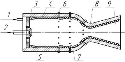
During internal cooling (Figure 1), the engine firing part is protected from burning out by creating a layer of gas and liquid near the wall at a lower temperature compared to the core temperature of the combustion zone. This layer is usually called the wall layer.
In the cooling process, both fuel 1 (Figure 1) and oxidizer 2 can participate, forming a thermal protection medium 3. For internal cooling, you must create a wall layer 4 (Figure 1), which is usually used for fuel, and squeeze the combustion zone from the firewall 5 of the combustion chamber. At the same time, fuel is fed into the combustion chamber through channel 7 (injectors) and forms curtains 7 that create several belts along the length of wall 5 (Figure 1).
Further, the burning stream through the narrowing 8 enters the jet nozzle 9, cooled by one or both fuel components.
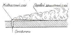
Figure 2 shows the mechanism for removing heat from the walls of parts in the hot zone of the engine due to the operation of the internal cooling system. At the same time the fuel Gorenje enters the combustion chamber (Figure 2) under the influence of the flow of combustion products spreads along the wall and a protective layer is created under the liquid layer, formed of two elements consisting of vapors and liquid. Due to the evaporation of the liquid, the thickness of the vapor layer over the liquid increases in the direction of the flow of combustion products. The process can proceed until all the liquid is lost, which causes a gradual erosion of the steam curtain. This does not prevent you from maintaining the thermal protection effect of the steam layer along the route length up to 100 mm. The thermal conductivity of the steam is significantly less than that of the liquid, so the thermal resistance of the steam component is several times greater than that of the liquid layer, and the main means of protection against overheating is the steam component, which has a greater thickness than the liquid layer.
When internal cooling is used, the cooler that additionally enters the combustion chamber does not participate directly in the combustion process and the total specific fuel consumption, in this case, increases in comparison with external cooling, which can worsen the technical and economic performance of the engine. Gorenje The analysis of Figure 2 and the experience of using the considered cooling systems shows that the most appropriate use is to protect the walls 5 (Figure 1) using a combined cooling scheme, in which the main heat removal is carried out by external cooling, and in the most heat-loaded places, protective curtains are additionally arranged according to the internal cooling scheme.
Indicators of thermal protection of the combustion chambers and the jet nozzle are enhanced by applying thermal protection coatings that have good erosion resistance and high adhesion to the walls of the product. Here you need to use materials that are more refractory than the walls 5 (Figure 1). Since refractory coatings usually have low thermal conductivity, their temperature (and therefore protective characteristics) is much higher than that of other materials used. Currently, metal carbides and oxides, ceramics and cermets with low thermal conductivity coefficients are mainly used as coating components. One of the most promising coatings is metal-ceramic based on zirconium dioxide, applied by plasma spraying. These coatings have a thickness of up to 600 microns and can withstand the temperature of gases on their surface over 2000 K. This ensures continuous operation of the engine for more than 400 seconds and more than 25 trouble-free starts.
Significant technological difficulties are caused by finishing the transition sections 8 (Figure 1) with coatings, especially with a small cross-section diameter of the narrowing section 9 of the combustion chamber. This problem was solved by using combined processing methods [4,5].
Working out the production processability of the surface for the operational requirements for coatings
The stability of the thermal protection element is provided in the process of working out the production processability of the surface of the parts of the hot zone of the engine for the operational requirements for coatings [6-9]. Thermal protection depends mainly on the condition of coatings, peeling and chipping of which can cause disruption of the thermal protection curtain, overheating of areas without coating and failure of the product. The main condition for obtaining a high-quality high-resource coating is to ensure its adhesive resistance relative to the walls of the combustion chamber and (if necessary) the jet nozzle. This is achieved by creating an artificial roughness obtained by jet-abrasive treatment, as well as applying a sublayer with high wettability relative to the nozzle wall.
Technological process of coating
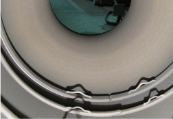
To ensure the required performance of the combustion chambers, before coating them, their borders are protected by removable screens in the form of expansion rings (such as those shown in Figure 3), which have spring properties and are equipped with locks in the form of an oblique section.
The latter allows compensating for changes in the size of the walls of hot zone parts that operate at a significant temperature gradient: from the outside of the liquid hydrogen to the temperature in the combustion zone on the inside, as well as at high pressure from the flow inside the pipelines. Gorenje Installation of protective elements complicates the development of the coating process, since the required continuous spraying process at its border (firewall - protective element) may cause surface cracks caused by differences in the physical properties of materials, surface conditions. So the roughness of the firewall made of copper alloy (even after joint sandblasting of the mating elements) is 2-3 times higher than the roughness of the steel protective element. The appearance of a non-calculated gap leads to a violation of the uniformity of the tight fit of the rings, causing the protective element to protrude into the flow zone, which creates an undesirable shielding effect. Due to this, in the area adjacent to the security element, there is a local increase in the thickness of the coating (due to the particles of powder material reflected from the protective element) and there may be a violation of the quality of the coating (the appearance of cracks and chips). The elimination of this phenomenon was made possible by using the technology developed with the participation of the authors for applying multi-layer coatings [2], which provides obtaining outer layers of increased thickness required to increase the product life.
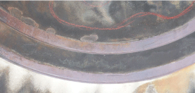
After applying a multilayer coating (Figure 4) and removing protective elements on the surface of the firewall, immediately behind the short circuit, a ledge from the coating is observed (Figure 5 and Figure 6) with underestimated (due to the effect of shielding and mechanical damage when removing the protective elements) strength properties of the coating.
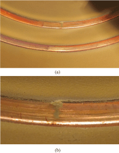
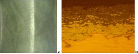
After applying the applied multi-layer coating (Figure 3), the protective elements are removed. So in most cases, was obtained the qualitative transitions of the coatings (Figure 4a), but in some cases under the influence of the shielding effect or due to the violation of technological process by the mechanical extraction of protective elements on the surface of the firewall in the coating may be an invalid ledge of the type shown in Figure 4b, which may cause deterioration of the operational properties of the coating. So the annular ledge in the path of the injected fuel component to cool the firewall in combination with disrupting the uniformity of flow of combustion products at the places of benches and a violation of a smooth transition (Figure 5) can lead to critical temperatures of the firewall and to its destruction.
The problem was solved by working out the technological modes on the witness samples and using the combined processing operation to ensure a smooth transition from the wall to the coating due to dimensional Stripping of the ledge edge.
Technological process of coating processing
The usually used method of cleaning coatings with abrasive circles of white electrocorundum often caused the effect of "salting" the working surface of the tool with viscous binding components of the multilayer coating (copper alloy, Nickel sublayer and nichrome bond in the coating). In addition, the use of abrasive wheels with small grinding grain sizes for finishing results in an increase in the complexity of cleaning the erosion-resistant coating, its overheating and a decrease in product characteristics. In addition, with small sections of the combustion chamber, the access of the abrasive wheel to the processing zone becomes difficult or impracticable.
In [5,6], new methods of combined processing with the imposition of an electric field are proposed, ensuring that the tool is allowed even with its one-sided approach to the processing zone.
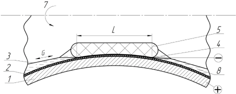
The use of combined processing methods (Figure 6) combines the processes of anodic dissolution of the conductive metal sheaf of the coating with the dimensional removal of irregularities from the protrusions of the abrasive grains fixed by the sheaf with abrasive granules. H the process of dimensional anodic dissolution during combined electroabrasive treatment allows reducing the pressure forces of the tool on the treated surface parts 1 and use a flexible tool in the form of a thin metal band 2 with an abrasive layer on the part of the part (the recommended grain size of the layer is 12 H). This allows one tool to align the micro-irregularities in any coating profile and distance from the drives 6; 7 of the tool to the processing zone 4 of the treated surface. The clamping force is provided by the clamping element 5, made in the form of a bag, inside which an air pressure of 0.05-0.1 MPa is applied. The clamping element is moved back and forth (6 in Figure 6) along with the belt 2 by flexible tension elements 3, which regulate the processing modes (tool pressure, cutting speeds, etc.). Tape 2 is connected to the cathode of the power supply with a voltage of 6-8 V. the Anode is a detail. The process takes place in a solution of weak electrolyte 8, supplied to zone L by irrigation. If there is no free access to the machining area, the clamping element 5 can be rotated in any direction 7 relative to the belt and the machining area of the part. The combined method of Stripping coatings avoids "salting", cauterization, eliminates local thinning of the layer, provides a smooth interface of areas that do not even have a free approach of the tool to the place of local processing.
Quality control of metal-ceramic coatings
Assessment of the quality of cleaning transition areas with blurring, such as performing a smooth interface, is performed visually at the first stage of control, in particular with the help of flexible light guides. As a criterion, the absence of a visible border of the transition between the smoothed surface of the firewall and the edge of the sublayer of the coating, visible in the form of a thin dark band, is accepted.
The quality of the coating after Stripping is evaluated by samples or by standard measurement of the height of the micro-surfaces. Figure 7a shows the transition area after Stripping, and Figure 7b shows the microchip of this element. Here is a transitional section of the coating, which was able to equalize the allowances due to the use of new technological processes. At the same time, the layer removed from the part does not exceed 100 microns, and the surface roughness after Stripping has decreased to Ra = 0.63 microns, which corresponds to the specified parameters.
Standard tests of samples of parts of the hot zone of the engine showed that the adhesive strength of the coating was at least 6 MPa at a given value of 4 MPa.
Conclusion
The conducted research allowed us to establish qualitative and quantitative indicators of the influence of the state of the surface layer of the transition areas of the applied heat-protective coatings on the performance characteristics of products. The advantages of [10,11] using a new scheme of combined processing with a flexible tool with the imposition of an electric field instead of traditional grinding are shown. It is established that the use of a flexible tool in the form of a conductive abrasive belt allows to expand the technological capabilities of finishing metal-ceramic coatings, replace the diamond tool with a more affordable abrasive tool, eliminate cauterization on parts and improve the performance of heat engines produced for rocket technology, including increasing the possibility of repeated use of products.
References
- Panichev EV, Smolentsev VP (2019) Surface preparation for applying a heat-resistant coating. Reinforcing technologies and coatings 15: 517-522.
- Smolentsev VP (2019) Mechanism of formation of high-resource heat-resistant coating. VGTU, Vestnik 15: 96-99.
- Ivanov VV, Smolentsev VP, Lebedev VA (2019) Chemical-mechanical bases of coating in vibration technology systems. Electroplating and surface treatment 15: 49-58.
- Suslov AG (2012) High-tech technologies in mechanical engineering. Mashinostroenie, Moscow, 528.
- Suslov AG (2019) Technologist's Handbook. Innovative engineering, 800.
- Safonov SV (2015) Technological support of product performance characteristics. VGTU, Voronezh, 224.
- Smolentsev VP, KondratievMV, Ivanov VV (2017) Design of technological processes for obtaining high-resource combined coatings. Reinforcing technologies and coatings 15: 273-281.
- Samsonov GV, Epik AP (1973) Refractory coatings. M. Metallurgy, 398.
- Baldaev LH (2007) Geothermal spraying. Market DS, Moscow, 344.
- Hasui A (1975) The technique of spraying. Mashinostroenie, Moscow, 288.
- Smolentsev VP (2006) Organizational and economic research in engineering. VGTU, Voronezh, 73.
Corresponding Author
Vladislav Smolentsev, Voronezh state technical University, Voronezh, Russia
Copyright
© 2021 Smolentsev V. This is an open-access article distributed under the terms of the Creative Commons Attribution License, which permits unrestricted use, distribution, and reproduction in any medium, provided the original author and source are credited.
