Modelling of Honeycomb Sandwich Structure with Curved Edges and Performing Analysis Using Finite Element Method
Abstract
The aim of the study is to perform FE Analysis using ANSYS for the Honeycomb sandwich structures with varying skin thickness ranging from 0.5 to 2 mm and edges of the honeycombs are converted into curve shapes to avoid any stress concentration at the intersection. The study of the natural frequencies of the structure is also carried out. The core structure is made up of Aluminum alloy and the skin or face sheet is made up of carbon fiber and the properties are been evaluated from ANSYS Engineering Data Source. The core has been modeled with a radius of curvature of 1.5 mm and different from conventional honeycomb structure with sharp edges, an increase in skin thickness has improved the load bearing capacity of the specimen.
Keywords
Honeycomb structure, ANSYS, Von-Mises, Deformation, Natural frequencies, Curved core structure
Introduction
The Honeycomb Structure or cellular materials are widely used in the Aerospace and Commercial industries due to their unique features such as lightweight and high strength-to-weight ratio [1]. They are often used to reduce the overall weight in the form of voids, these sandwich structures have high axial stiffness and have a wide range of applications from transportation, aerospace, marine, railways and automobile. The sandwich structure has three components mainly core, and skin or faces sheets [2]. The core is made of lightweight usually from alloy, wood and polymeric foams, the strength and stiffness of the honeycomb structure depend on the material used in making.
Honeycomb structures have minimal density, high strength, and out-of-plane compression properties because of hollow cells, usually, they are made with corrugation and expansion process and the widely used material are Aluminum, fiberglass, carbon-fiber, and reinforced plastic, they possess both high strength-to-weight ratio and high-stiffness-to -weight ratio [3].
In the Aerospace industry, marine and automobiles we need a lightweight and high strength materials without compromising the structure [4], honeycomb structures are considered one of the types which exhibits the qualities and also the natural frequencies are comparatively high which can help us prevent the structure from collapsing and failure due to the resonance.
Material Properties
The Honeycomb structure used in this study consists of three components and is made of two materials. The materials that are used from the ANSYS Engineering Material Data Sources are Aluminum Alloy and Carbon fiber (290GPa) with all the properties which are predefined in the ANSYS. Carbon Fiber exhibits excellent tensile properties. low density, high thermal stability with creep resistance due to their continuous fibers and 0° orientation is the most popular [5] (Table 1).
Aluminum Alloy has very good weldability and excellent corrosion resistance, high strength-to-weight ratio and resilience which makes it more suitable for the marine and aerospace industry and they are easily available in the market, have a density of 2770 kg/m3, Young's modulus 72 GPa and Poisson's ration 0.33.
Numerical Investigation
Geometry of the model
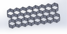
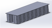
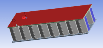
The cell geometry is modeled in SOLIDWORKS and then imported into ANSYS to perform Finite Element Analysis [6]. In general, the finite element is in the form of a partial differential equation and the solution is usually obtained by applying boundary conditions and load before FE analysis is set to run. The SOLIDWORKS model [7] is first created with core thickness, edge length and height of the honeycomb and also additionally in this study we have edges being curved (Figure 1, Figure 2 and Figure 3).
Figure 1 shows the model of the cell geometry with tc = 0.5 mm, Edge length = 10 mm and core height (hc) is 30 mm and the curved edge length is 1 mm. Different models with varying face sheet or skin thickness are created with 0.5 mm, 1 mm, 1.5 mm and 2.0 mm and assembled with the core. All geometries are modeled in the SOLIDWORKS. Then the file is imported to ANSYS to perform FEM Analysis [8] for all the geometries with the same boundary and load conditions as shown in Figure 4.
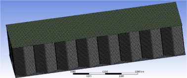
In the ANSYS quadrilateral elements as shown in Figure 3 are used instead of triangle or linear, because the number of nodes of a quadrilateral is higher than the triangular element [9]. The Quadrilateral element has 8 nodes and the triangle has 3 nodes which could manipulate the FEM analysis and would reduce the precision in the results compared to the Quadrilateral, the total number of nodes and elements obtained from Mesh are 617195 and 89990 respectively.
Boundary Conditions
The Honeycomb structure is modeled, and analysis is performed with two studies, one is the natural frequency by modal analysis [10] obtained for all the varying skin or face sheet thickness which is shown in Figure 4. The second one involves the static structural where Von-misses and Deformation are calculated by applying the boundary conditions for the analysis with the edges being fixed on both sides and modeled similar to simply supported beam with applied loads on the top face sheet or skin with varying from 100 Pa to 700 Pa and the study is being conducted (Figure 5 and Table 2) [11].
Results and Discussion
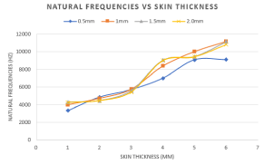
The Modal analysis calculated shows the natural frequencies for the thickness varying from 0.5 mm to 2.0 mm and we obtain the values from ANSYS for the first 6 and tabulated them. It is observed that the natural frequencies increases along with the thickness and the highest natural frequency is observed at 1.0 and 1.5 mm which are 11179, 11156 respectively.
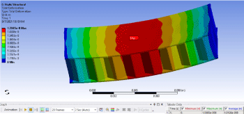
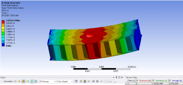
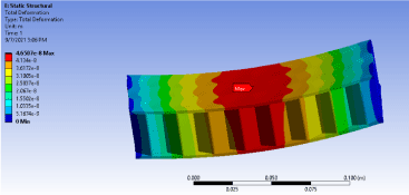
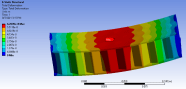
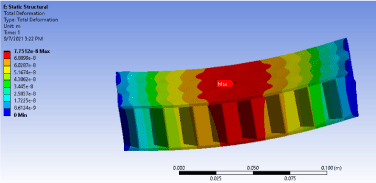
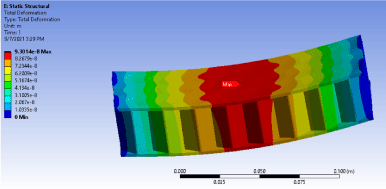
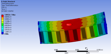
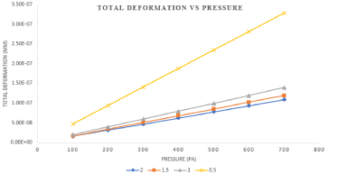
Figure 6 shows the total deformation of the specimen from 0.5 mm to 2.0 mm thickness which is subjected to loads from 100, 200, 300, 400, 500, 600 and 700 PA all the forces are applied uniformly distributed across the face sheet thickness and the results show that, the total deformation reduces significantly with the increase of the skin thickness [12]. The maximum deformation was located at the center of the specimen where the bending occurs.
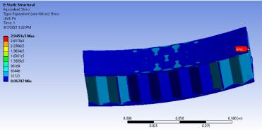
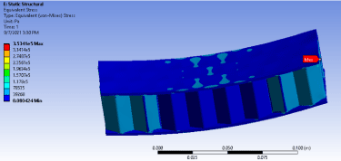
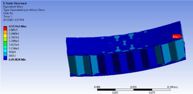
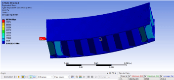
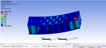
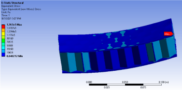
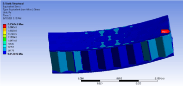
Similarly, Figure 7 shows the calculated Equivalent Von-Mises Stress for the various face sheet thickness which is subjected to the same loads uniformly distributed from 100 PA to 700 PA. We observe that the equivalent stress decreases drastically with the increase in face sheet thickness, the maximum stress is obtained was 795510 N/m2 at 0.5 mm face sheet thickness at 700 Pa applied and the minimum stress obtained was 58901 N/m2 at 100 Pa. The stress location was at the edges of the specimen.
Conclusion
The Finite element modeling has been used under Software (Ansys) for the Honeycomb Structure with curved edges of the core. The Natural frequencies are evaluated under different skin thicknesses are described and compared in Table 2 and Figure 5 and calculated the Total deformation and equivalent stress for the various geometries [13] with varying loads from 100 to 700 Pa during static structural domain which is plotted and shown in Figure 8 and Figure 9. This study shows with the increase in skin thickness contributes more resistance to deformation.
The Natural frequencies tend to increase with thickness increased from 0.5 to 2.0 mm and the equivalent stress has been decreased with increase in skin thickness and maximum total deformation was for the 0.5 mm thickness and the minimum deformation was found for 2.0 mm thickness and the location was found at the center of the specimen and also the Table 2 and Figure 5 shows the variations of the natural frequencies with the thickness being varied.
The increase of thickness has a significant impact on the behavior of the Honeycomb structure and also the force transmitted to the core, in this case the honeycomb has been modeled in a curve shape at the edges compared to conventional with sharp edges, the more thickness implies the stress has been under control and less prone to failure and has a wide range of acceptable applications in the engineering [14].
References
- Beyle A (2019) Predicting the viscoelastic behavior of polymer composites and nanocomposites. In: Rui Miranda Guedes, Creep and fatigue in polymer matrix composites. Woodhead Publishing, Oxford, UK, 157-214.
- Nurhaniza M, Ariffin MK, Ali A, et al. (2010) Finite element analysis of composites materials for aerospace applications. IOP Conf Ser: Mater Sci Eng 11: 012010.
- Rui Miranda Guedes (2019) Creep and fatigue in polymer matrix composites. Woodhead Publishing, Oxford, UK.
- Nilsson E, Nilsson AC (2002) Prediction and measurement of some dynamic properties of sandwich structures with honeycomb and foam cores. J Sound Vibr 251: 409-430.
- Rupani S, Dev R, Jani S, et al. (2017) Experimental evaluation of coefficient of thermal expansion of carbon fiber reinforced polymer tube.
- Shrigandhi GD, Deshmukh P (2016) Modal analysis of composite sandwich panel. International Journal of Current Engineering and Technology.
- Nurhaniza M, Ariffin MK, Ali A, et al. (2010) Finite element analysis of composites materials for aerospace applications. IOP Conf Ser: Mater Sci Eng 11: 012010.
- Beyle A, Ibeh CC (2011) Predicting the viscoelastic behavior of polymer nanocomposites. In: Rui Miranda Guedes, Creep and fatigue in polymer matrix composites. Woodhead Publishing, Oxford, UK, 184-233.
- Gir Nitin Ratan, Patel AZ, Ghalke AB (2016) FEA and experimental analysis of Honeycomb sandwich panel using glass fiber. Int J Mech Eng 4: 16-23.
- Kim HY, Hwang W (2002) Effect of debonding on natural frequencies and frequency response functions of honeycomb sandwich beams. Compos Struct 55: 51-62.
- Shubham Upreti, Vishal K Singh, Susheel K Kamal, et al. (2020) Modelling and analysis of honeycomb sandwich structure using finite element method. Material today: Proceedings 25: 620-625.
- Matta Vidysagar, Suresh Kumar J, Venkatarviteja Duddu, et al. (2017) Flexural behaviour of aluminum honeycombcore sandwich structure. IOP Conf Ser: Mater Sci Eng 197: 1-11.
- Tarnopol'skii YM, Beil AI (1983) Problems of the mechanics of composite winding. In: Kelly A, Mileiko ST, Handbook of Composites. Elsevier Science Publishers BV, 45-108.
- Tarnopol'skii YM, Portnov GG, Beil AI (1982) Technological problems in composite winding mechanics. In: Obraztsov IF, Vasil'ev VV, Mechanics of Composites. MIR Publishers, Moscow, 186-222.
Corresponding Author
Sai Krishna Pinnamaneni, Department of Mechanical and Aerospace Engineering, The University of Texas at Arlington, Arlington, Texas, USA
Copyright
© 2021 Pinnamaneni SK. This is an open-access article distributed under the terms of the Creative Commons Attribution License, which permits unrestricted use, distribution, and reproduction in any medium, provided the original author and source are credited.
