An Experimental Investigation of the Vortex Merging over a Cranked-Delta Wing at Subsonic Speed
Abstract
A series of experiments was carried out to investigate the aerodynamic characteristics of a cranked-delta wing model. It has been noted by various researches that in the vicinity of the take-off angles of attack, an instability in the longitudinal stability of aircraft equipped with cranked delta wings occurs where its origin is not well understood yet. To further study this phenomenon, a semi-span cranked delta wing model was designed and built. Surface pressure data for various angles of attack at low subsonic speeds, to better simulate take-off and landing conditions, were measured. The only test limitations of concern were inaccessibility to an accurate balance to measure forces and moments and to correlate them with the surface pressure data. However, analysis of the surface reassure data showed formations of two distinct strong vortices over the wing surface with strong suction peaks at their cores. The interaction between the two vortices increased with angle-of-attack, and as a result, the outer vortex moved inward while the inner vortex moved outward. At a certain angle-of-attack, these vortices merge with each other and at higher angles of attack the vortex breakdown moved onto the wing surface and as a result, the suction peak collapsed and spread in the spanwise direction. Surface pressure data clearly shows that the angle of attack where the vortex burst moves onto the wing surface correlates well with the previous studies regarding the mentioned longitudinal instability. These findings could help designers to optimize the crank angles to avoid such an undesired phenomenon.
Keywords
Cranked-delta wing, Vortex interaction, Suction, Pressure distribution, Breakdown
Introduction
Modern fighter aircraft are equipped with low aspect ratio large leading-edge sweep angle wings to improve their efficiency and maneuverability. In recent years, many investigations have been conducted on delta wing characteristics at low speeds and at high angles-of-attack [1-10]. At subsonic speeds and at moderate to high angles-of-attack, a pair of vortices forms over the suction surface of delta wings with sharp leading edges. These vortices dominate the flow-field over the wing surface and create an additional lift force called vortex lift that are very beneficial during landing , take-off and above all maneuvers [4]. However, as the angle-of-attack is increased, a sudden phenomenon in the structure of this vortices called vortex breakdown occurs that changes the aerodynamic characteristics of these wings. Gursul, et al. [2] studied unsteady aerodynamics of nonslender delta wings such as shear-layer instabilities, leading-edge vortices and vortex breakdown. Elsayed, et al. [1] used Stereo Particle Image Velocimetry (SPIV) to investigate the unstable flow phenomena and characteristics of the vortex flow over a delta wing model at moderate to high angles-of-attack. Verhaagen, et al. [7] studied effects of the leading-edge shape on the flow behavior over nonslender delta Wings. Zhang, et al. [10] studied unsteady characteristics of the burst vortices over a slender delta wing model. Their analysis of the pressure signals showed that the spiral wave of the burst vortex flow over the wing surface was the primary part of the pressure fluctuations and the buffeting of the slender delta wing is mainly due to this spiral wave. Yayla, et al. [9] investigated effects of the angle-of-attack variations on the flow structure over a nonslender lambda wing via particle image velocimetry (PIV) technique.
Nowadays, double delta wings are used in most high maneuverable aircraft to further increase their performance characteristics as well as their maneuverability. Brennenstuhl, et al. [11] investigated vortex interactions between the inner and the outer vortices as well as the vortex breakdown phenomenon. Verhaagen [12] compared the aerodynamic characteristics of delta and double delta wings with each other. They showed that by adding a strake to a delta wing, two additional vortex systems were formed over the wing surface that significantly increased the lift force at moderate to high angles-of-attack. However, the vortex structure over a double delta wing model is much more complex due to the interaction of the strake and the main wing vortex, uneven burst of vortices, etc. to name a few. As a result of the aforementioned complexities, many researchers tried to study this complex behavior of the vortices experimentally and/or numerically [11-27]. Hoeijmakers, et al. [20] studied vortex flow over double delta wings and found that due to the interaction between strake and wing vortices, the wing vortex increases in strength as it is fed from both the vorticity from the wing leading edge and the shear layer emanating from the strake leading edge. Thompson [24] investigated the effects of variations in angle-of-attack, leading-edge kink angle, Reynolds number, leading-edge cross-section shape on the vortex structure through visualization study of the vortex flow around double delta wings. Olsen and Nelson [22] studied interaction of a double delta wing vortices via visualizing the flow field over the model in a wind tunnel. Hebbar, et al. [19] conducted extensive flow visualization studies and investigated the influence of Reynolds number on the vortex interactions/trajectories, and vortex breakdown. Verhaagen [26] investigated effects of the Reynolds number on the flow over a double-delta wing and found that Reynolds-number had strong effects only on the flow field over the suction side of the wing. Gai, et al. [15] investigated vortex interaction and breakdown over double delta wings and investigated the role of fences in the vortex interaction mechanisms. Rao, et al. [23] performed experiments on a round leading-edged double-delta wing model at subsonic and transonic speeds and indicated that a complex phenomenon emerges due to the strake and wing vortices. Zhang, et al. [27] studied interactions between the strake and wing vortices over a double delta wing using particle image velocimetry measurements. Dehghan, et al. [14] conducted flow visualization studies over a cranked-double delta wing. Kumar, et al. [21] studied the effect of leading edge shapes on a double delta wing at low speeds.
The previous investigations were conducted only for a typical double delta wing configurations with higher sweep angle on the inner leading-edge (Λin > 75°). These studies focused mostly on the outer vortex behaviors because the inner wing had relatively small area and was designed using the concept of the vortex enhancement caused by the leading-edge strakes. On the other hand, cranked-delta wing has a smaller inner sweep angle and a relatively large inner wing area when compared to a double delta wing. There are only a few studies that investigated the vortex interactions over a cranked-delta wing. In the present study, wind tunnel tests were carried out to investigate the vortex behavior on a half-span cranked-delta wing model that has a relatively small inner leading-edge sweep angle. The vortex behavior for this type of wing is different with that of the typical double delta wing configurations which has been previously considered by several researchers. Almost all of the previous investigation of the vortex behavior over cranked-delta wing were based on balance force measurements and/or flow visualization. The study of vortex phenomenon over theses wings based on the surface pressure distribution is very limited. Therefore, to further fill the existing gap in our knowledge of the complex flow characteristics over cranked-delta wings, the surface pressure distribution over the suction side of a model of this type of wing at various conditions were obtained. The data were used to study the vortex formation, merging, and breakdown.
Cranked-Delta Wings
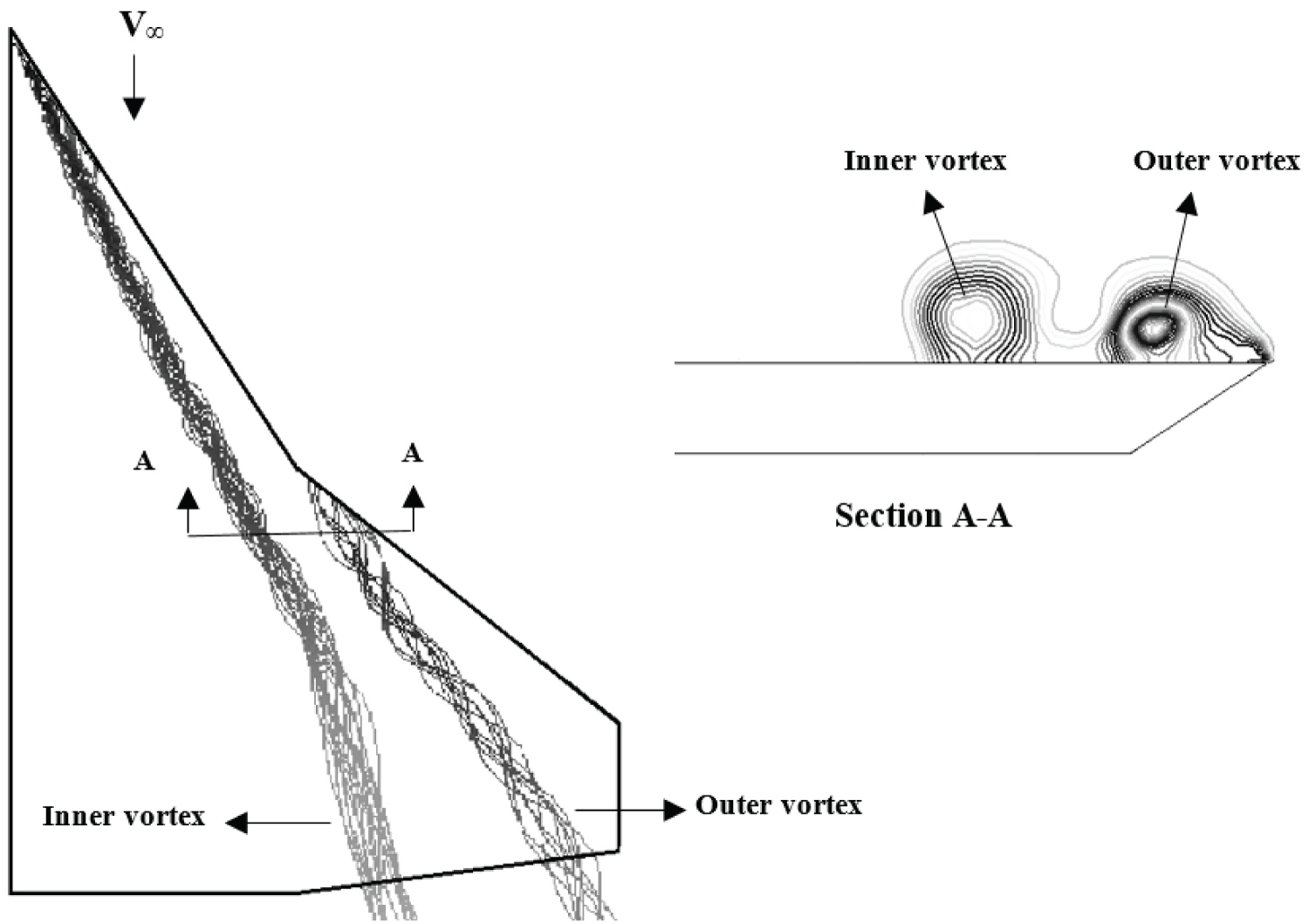
The flow field over cranked-delta wings at moderate angles-of-attack is dominated by two strong vortices. As shown in Figure 1, the inner vortex is shed from the wing apex while the outer vortex is shed from the kink portion of the leading-edge. The inner vortex induces a lateral velocity field which energizes the boundary layer on the outer wing's upper surface where the flow has separated from the kink portion of the leading-edge. This stabilizes the flow of the outer wing vortex which is relatively weaker that the inner one and is subject to disturbances. The two vortices rotate in the same direction, hence they tend to move around each other. At moderate and high angles of attack downstream of the leading-edge kink, the two vortices interact by coiling about each other. Near the trailing-edge, due to the interaction between the vortices, the outer vortex is fed through both the outer leading-edge and the shear layer of the inner vortex and as a result the outer vortex is much stronger than the inner one. The interaction between the two vortices causes the outer vortex to move inward and the inner one is forced to move outward. At higher angles of attack, these vortices merge with each other and at a certain angle of attack the vortex breakdown moves onto the wing surface and as a result the suction peak collapses and spreads in the spanwise direction. Vortex breakdown induces nonlinear aerodynamics and may results in the loss of performance and stability of the aircraft which will limit flight regimes of high speed aircraft.
Experimental Setup
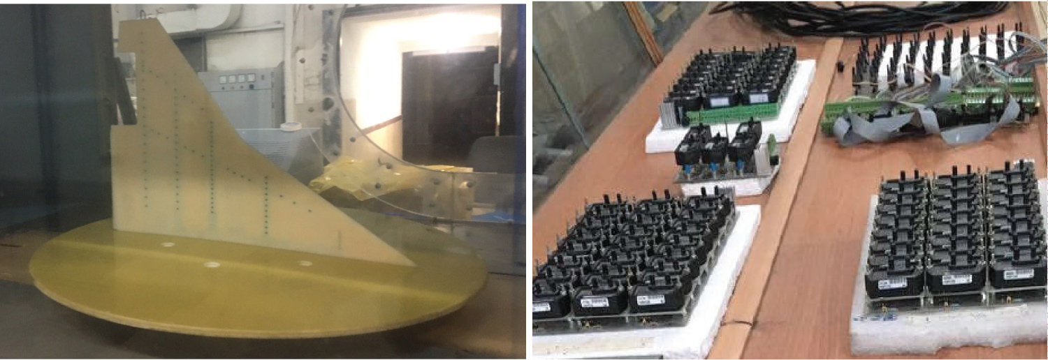
The experiments were carried out in a low speed open circuit, suction type wind tunnel. This tunnel has a rectangular test section of 80 × 100 cm2 and is equipped with three anti-turbulence screens and a honeycomb in its settling chamber. All tests were conducted at a constant Reynolds number of 0.52 × 10⁶ based on the root chord of the model. The angles-of-attack were varied from zero to 30 degrees. A half-span sharp edged cranked-delta wing model was constructed for these experiments (Figure 2).
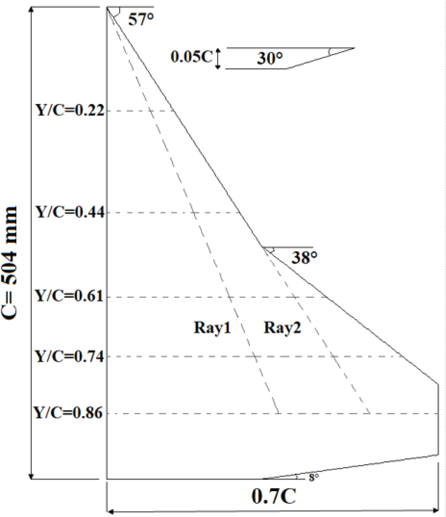
The inner wing had a sweep angle of 57 degrees and the outer wing had a sweep angle of 38 degrees. To minimize the influence of the wind tunnel floor boundary layer, the semi-span wing was mounted on a circular splitter plate [28]. In the present study, the pressure distribution over the wing surface was measured along five spanwise stations as well as two ray stations as shown in Figure 3. Surface pressure distribution over the wing surface was measured using 106 pressure transduces with pressure ranges of 5 mbar to 24 mbar with an accuracy of 0.25% of their full-scale and with a minimum frequency response of 1 KHz, Figure 2. To further examine the vortex behavior via examining the root mean square (RMS) of the pressure fluctuations, the tube length and the material that gave the minimum time lag for all applied pressures were selected. Two A/D boards were employed for the pressure transducers. All data from the pressure transducers were sampled simultaneously at a frequency of 1 kHz for more than 6 seconds. The uncertainty of the measured pressure data were calculated by the method of Kline and McKlintock [29]. The maximum absolute uncertainty of the measured pressure coefficient is estimated to be 1.9% of the full scale of the transducers.
Results and Discussion
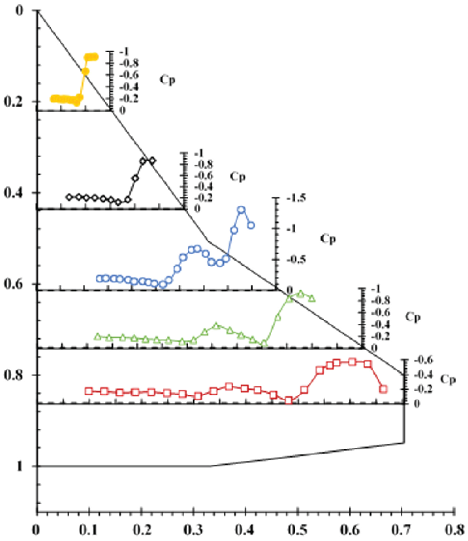
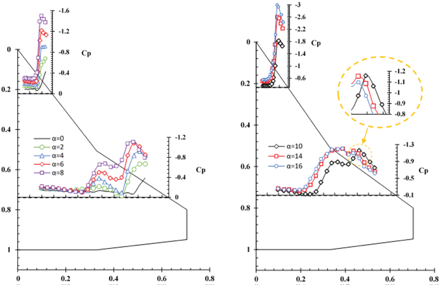
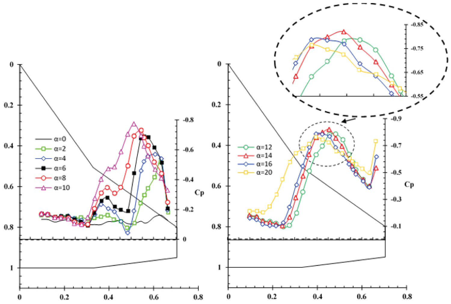
Figure 4 shows the spanwise pressure distribution over the upper surface of the model at an angle-of-attack of 4 degrees for all stations, Y/C = 0.22-Y/C = 0.86. The stations Y/C = 0.22 and Y/C = 0.44 are underneath the inner vortex only and as a result the pressure distribution for these stations has one suction peak, Figure 4. On the other hand, the stations located at Y/C = 0.61, Y/C = 0.74 and Y/C = 0.86 are affected by both inner and outer vortices and the pressure distribution curves for these stations are seen to have two suction peaks corresponding to the core of the inner and the outer vortices. As the vortices move downstream, their strengths decrease, so the suction peak is largest near the apex and decreases in the downstream direction toward the trailing edge. The distance from the first station, Y/C = 0.22, to the wing apex, where the sweep angle is 57 degrees, is approximately equal to the distance from the third station, Y/C = 0.74, to the kink of the model, where the sweep angle is 38 degrees, Figure 3. The pressure distribution for these two sections, for several angles of attack is shown in Figure 5. The vortices are formed over the wing surface at an angle-of-attack of approximately 2 deg. The suction peak of the inner vortex at Y/C = 0.22 is seen to be equal to the suction peak of the outer vortex at Y/C = 0.74 for an angle-of-attack of 2 degrees. Up to an angle-of-attack of 4 deg., the two vortices have the same strength. At an angle-of-attack of 6 deg., the strength of the inner vortex at Y/C = 0.22 is greater than that of the outer vortex at Y/C = 0.74 and the suction peak at Y/C = 0.22 is larger than the suction peak of the outer vortex one at Y/C = 0.74. Beyond an angle-of-attack of 8 deg., the inner vortex becomes stronger and its core axial velocity as well as its suction peak increases rapidly.
On the other hand, the strength of the outer vortex decreases with angle-of-attack and as a result, the vortex strength and hence its core axial velocity remains relatively constant for angles-of-attack of 10° to 14°, Figure 5, thus its suction peak has a constant value in the pressure distribution curve. At an angle-of-attack of 16 deg., the outer vortex suction peak decreases slightly, hence it seems that the outer vortex is burst, Figure 5. However, one should note that once the vortex burst reaches the trailing-edge, it may jump upstream without any change in the angle-of-attack or other flow conditions [6].
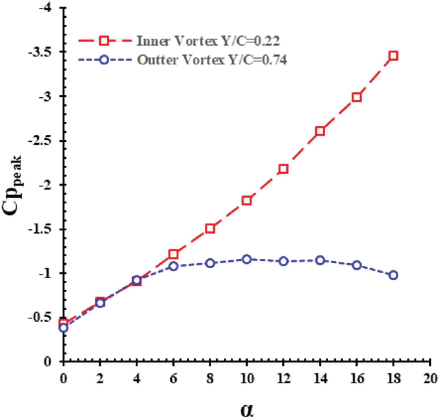
Figure 6 compares the effects of angles-of-attack on the minimum pressure coefficient of the inner vortex core at section Y/C = 0.22 with that of the outer vortex core for station Y/C = 0.74. It is clearly seen that Cpmin for both stations are identical up to an angle-of-attack of 4 deg. The inner vortex is fed through the leading-edge with higher sweep angle and is strong enough to recirculate the flow at higher angles-of-attack, Figure 6. On the other hand, the outer vortex is fed from the leading-edge with lower sweep angle, Λout = 38°, its strength at higher angles-of-attack decreases, and its core pressure coefficient, Cpmin, is approximately constant from 10° to 14°. As seen from Figure 6, at station Y/C = 0.74, the minimum pressure coefficient increases for angles-of-attack of 16 deg. and beyond, therefore, the outer vortex seems to have been burst for angles-of-attack beyond 16 degrees while that of the inner one does not seem to be burst up to angles-of-attack of 18 degrees and beyond.
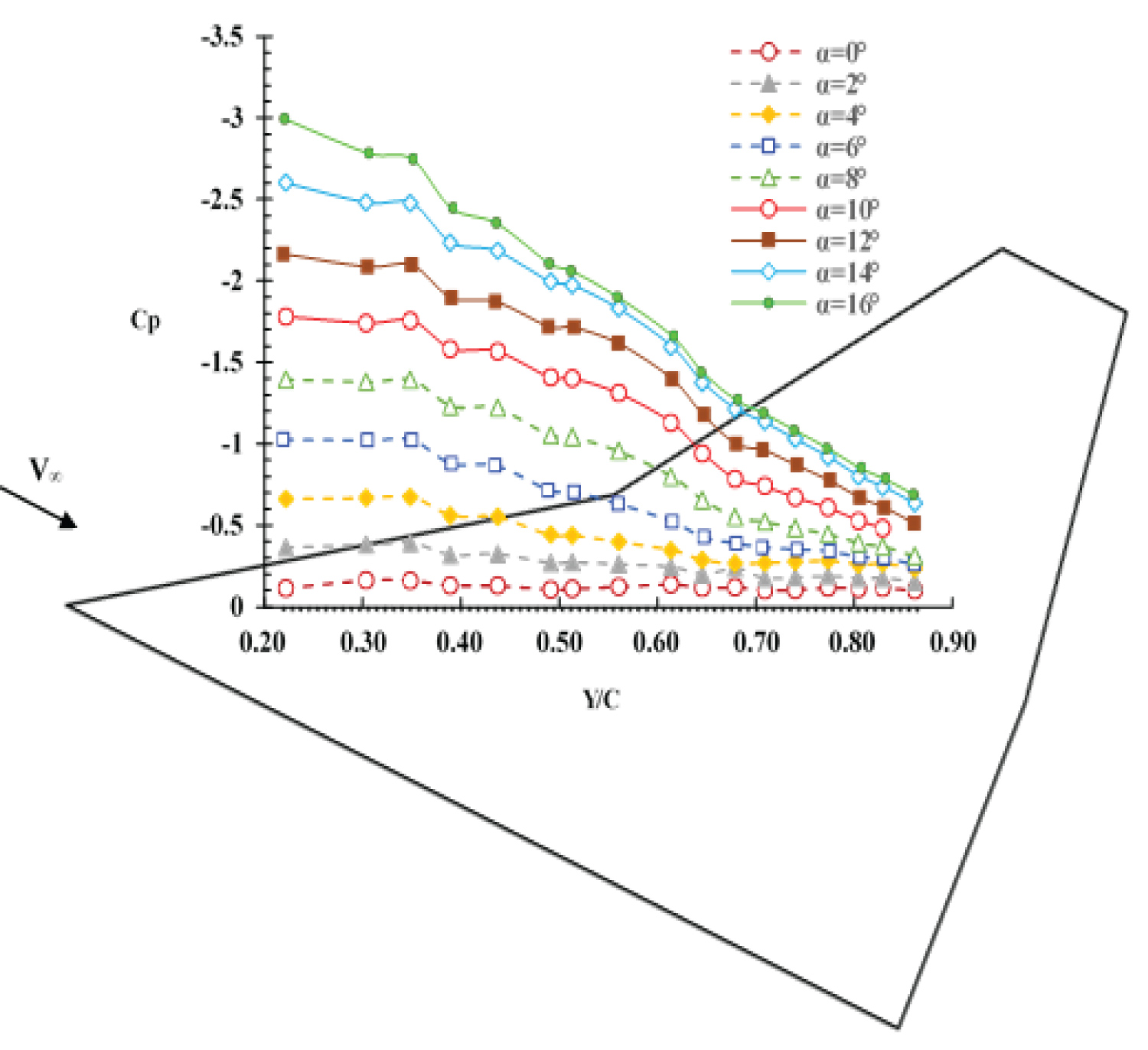
Figure 7 shows the effect of angles-of-attack on the pressure distribution at section Y/C = 0.74. Downstream of the kink of the wing leading-edge, the inner vortex is no longer fed with vorticity from the inner leading-edge and its strength decreases due to the viscous effects. The lateral velocity caused by the inner vortex supplies kinematic energy to the outer vortex. Therefore; the local strength of the outer vortex is greater than that of the inner vortex, Figure 7. As the angle-of-attack is further increased, the vortices widen and cover a large portion of the wing surface, thus the two vortices interact with each other, the outer vortex moves inward and the inner vortex moves outward. Beyond an angle-of-attack of 6 deg., as a result of the higher sweepback angle of the inner wing, Λin = 57°, the rate of growth of its strength along with its corresponding suction peak increases more than that of the outer vortex, Figure 7. Therefore; at an angle-of-attack of 14 deg., the local strength of the inner vortex is greater than that of the outer vortex and its suction peak is larger.
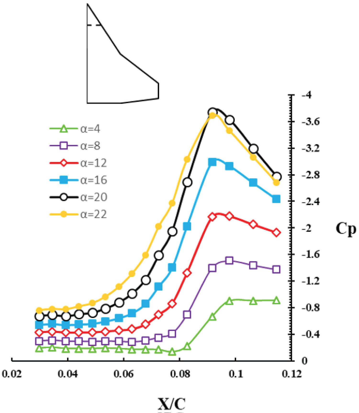
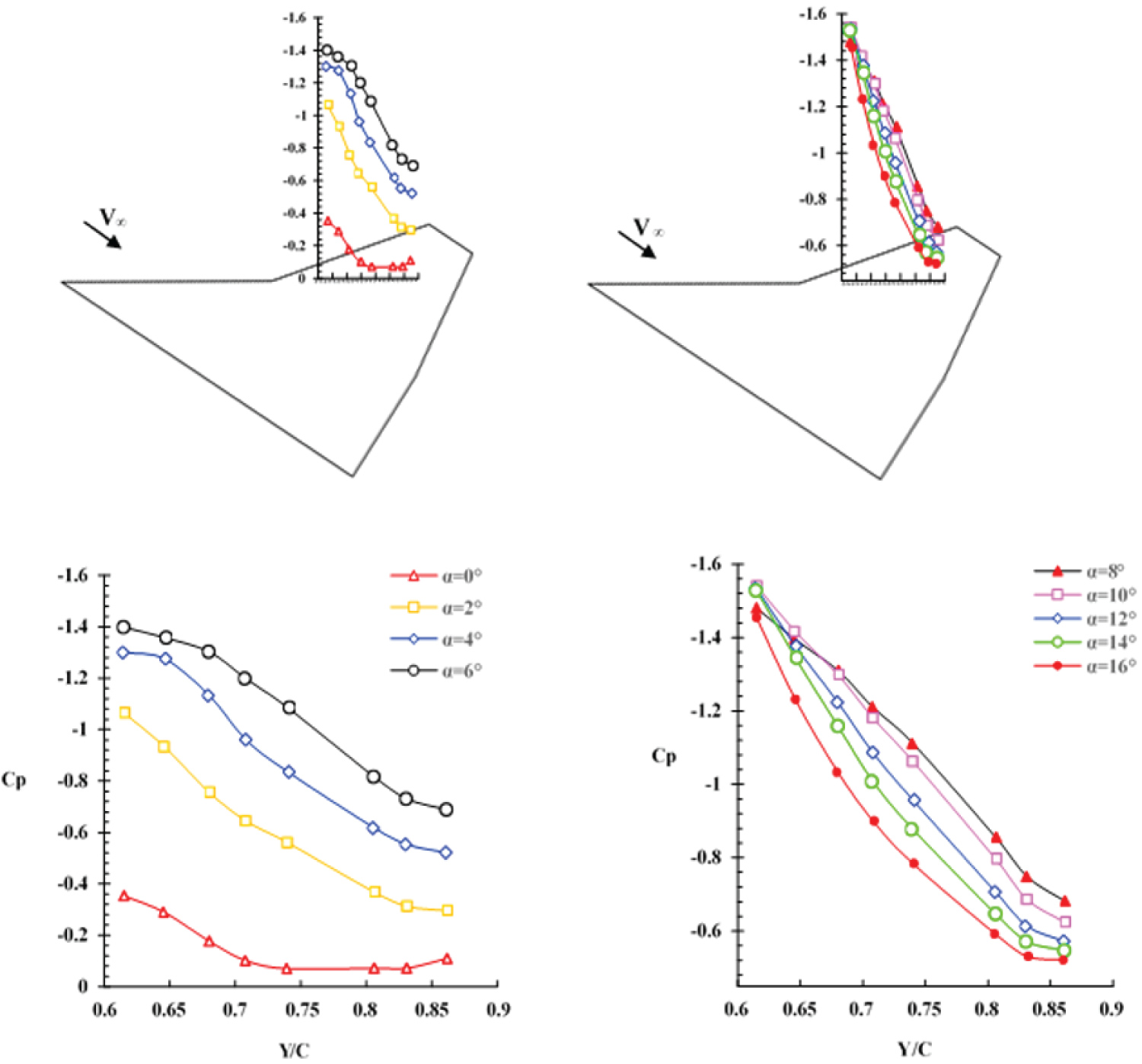
Figure 8 shows the surface pressure distribution at a station Y/C = 0.22 for several angles of attack. As the angle-of-attack is increased from 4 to 20 deg., the inner vortex becomes stronger and its suction peak increases. At an angle-of-attack of 20 deg., the pressure distribution is seen to have reached its maximum value, peak suction value, minimum . The pressure distribution at station Y/C = 0.44 is similar to that of Y/C = 0.22, Figure 9. As the vortex moves downstream, its strength decreases and as a result the suction at this station, Y/C = 0.44, is less than that at Y/C = 0.22 for all angles-of-attack considered in these tests.
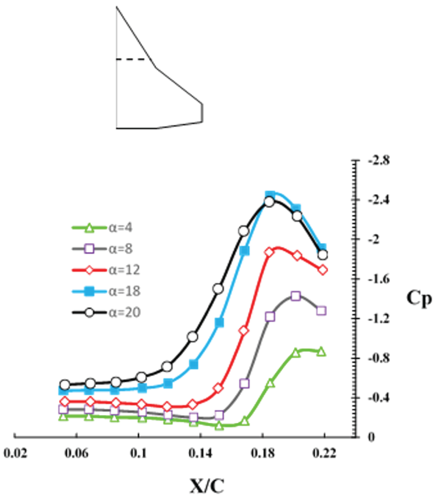
Figure 10 shows the spanwise pressure distribution at a station Y/C = 0.86 for various angles-of-attack. A very weak suction peak due to the weak inner vortex and a stronger one due to the outer vortex are observed at 2 degrees angle-of-attack. As the angle-of-attack is increased, both vortices cover a large portion of the wing and as a result the interaction between the inner and the outer vortices increases. Due to the mutual induction between both vortices, the suction peak of the outer vortex moves inward and that of the inner vortex moves outward, therefore, the initial distance between the two peaks decreases, Figure 10. At 10 degrees angle-of-attack, this station, Y/C = 0.86, seems to lie in the merging region of the two inner and outer vortices. As the angle-of-attack is further increased to 12 degrees, the length of the merging area decreases and finally at 14 degrees angle-of-attack, the two suction peaks merge into a single peak. Further increase in the angle-of-attack results in the vortex breakdown point moving onto the wing surface and affecting the pressure distribution at this station, Y/C = 0.86, and as a result the suction peak is seen to decrease, Figure 10, .
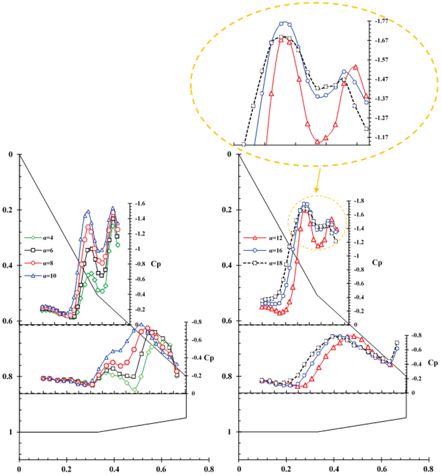
From Figure 11 it is found that as moving downstream, the vortex interaction becomes more prominent. At station Y/C = 0.61, as the angle-of-attack is increased, the outer vortex core remains at a fixed position while that of the inner vortex deviates slightly toward the root chord, thus it can be assumed that the shear layer of the inner vortex is completely detached from the outer vortex. On the other hand, as the vortices move downstream, their size is increased and the interaction between them becomes stronger. In addition, downstream of the wing kink, the entire vorticity shed from the outer leading-edge is fed into the outer vortex, therefore, the rate of growth of the outer vortex strength increases with angle-of-attack as the trailing edge is approached, Figure 11. At station Y/C = 0.86 in Figure 11, it is noted that with increasing the angle-of-attack, the interaction between the two vortices becomes stronger and the outer vortex core along with its corresponding suction peak move inward while the inner one and its suction peak move outward. As a result, the distance between the two cores is reduced and finally the two vortices appear to merge with each other, Figure 11, station Y/C = 0.86, . At station Y/C = 0.61, the enhancement of the vortices strength and their expansion over the wing surface with increasing angle-of-attack is more pronounced, Figure 11. Up to an angle-of-attack of 8 deg., the local strength of the outer vortex is greater than that of the inner one, Figure 11, station Y/C = 0.61. At this station, Y/C = 0.61, the size of the vortices are not large enough, hence the distance between the core of vortices is considerably large and no interaction between the two vortices, inner and outer, is observed. Thus the outer vortex is not fed by the shear layer of the inner vortex and the rate of increase in its strength with angle-of-attack is less than the corresponding one but at station Y/C = 0.86, Figure 11. At an angle-of-attack of 10 deg., the local strength of the two vortices, inner and outer, is approximately equal, and at 12 deg. angle-of-attack, the inner vortex strength becomes greater than that of the outer vortex. The inner vortex suction peak remains constant from angles-of-attack of 10 deg. and beyond, and finally it decreases as the vortex burst reaches this station, Y/C = 0.61, at an angle-of-attack of about 16 degrees. The inner vortex core seems to collapse at an angle-of-attack of about 18 degrees, Figure 11, station Y/C = 0.61.
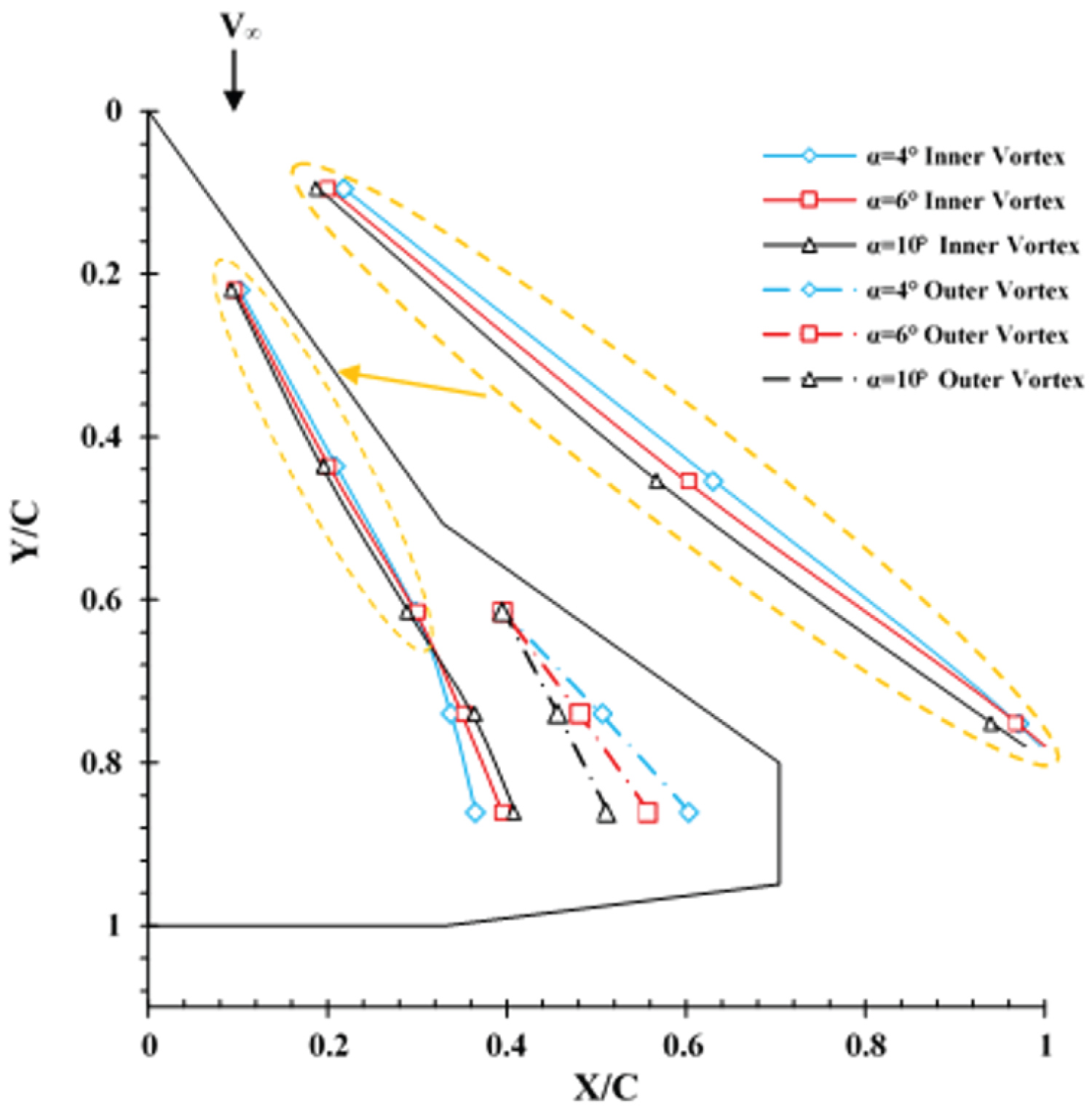
Figure 12 shows the vortex trajectories for both inner and outer vortices at three different angles-of-attack, α = 4, 6 and 10 degrees. Note that the position of the inner and outer suction peak marks the spanwise location of the inner and outer vortex core. Beyond 10 degrees angle of attack, the vortex system on the wing surface enlarges and it is hard to distinguish the vortex core from the surface pressure data. At stations Y/C = 0.22 and Y/C = 0.44 which are the only stations affected by the inner vortex, the vortex core moves slightly toward the wing root chord, Figure 12. At stations underneath both inner and outer vortices, Y/C = 0.61, 0.74 and 0.86, as both the angles-of-attack and Y/C are increased, the vortices are widen and they cover a large portion of the wing surface and as a result, the interaction between them increases. At stations Y/C = 0.74 and Y/C = 0.86, the outer vortex is seen to move inward toward the wing root chord while the inner vortex moves slightly outward. Thus, the initial distance between the two vortex cores decreases, as both the angles-of-attack and Y/C are increased.
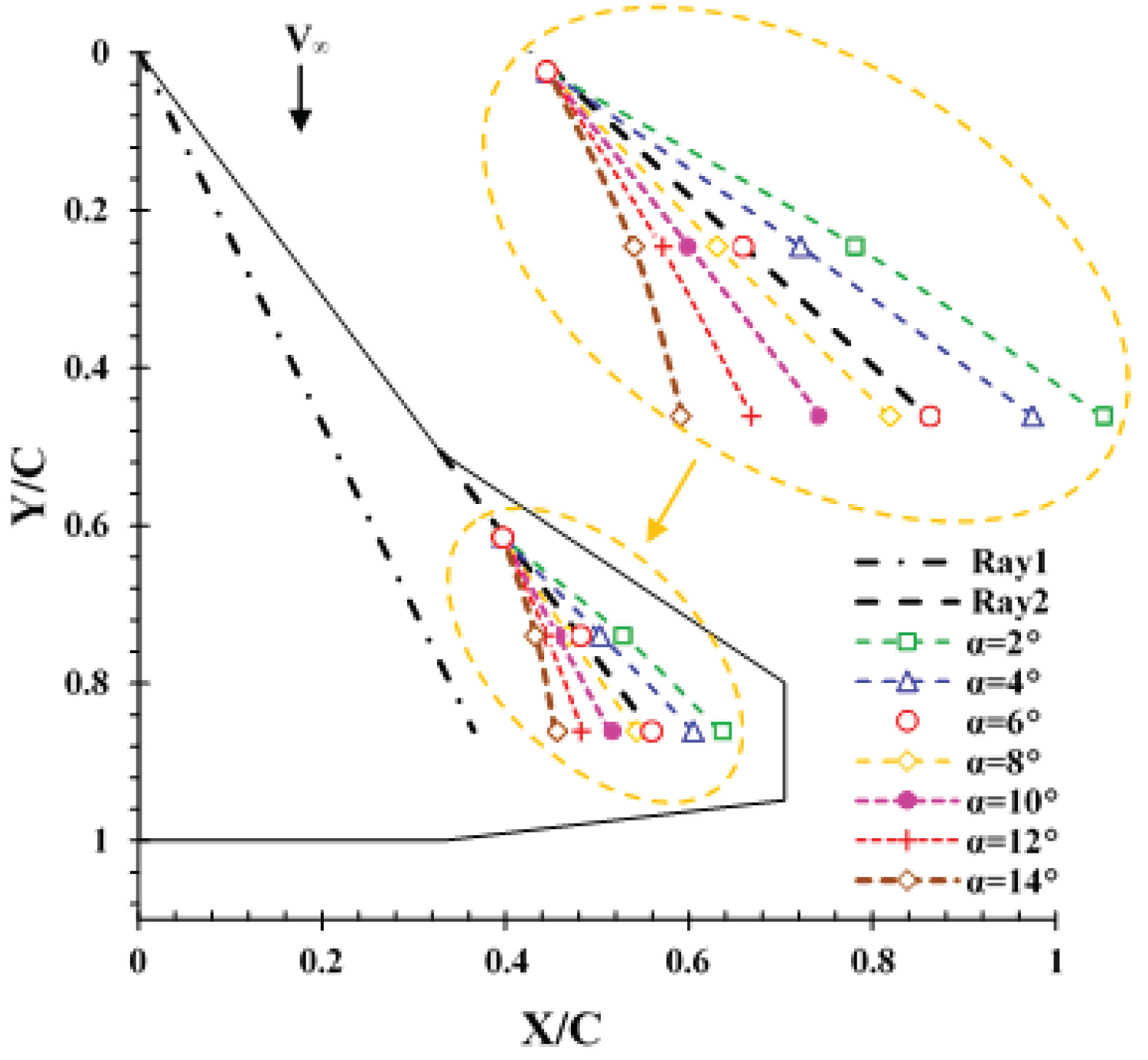
Figure 13 shows locations of the outer vortex core for various angles-of-attack. From Figure 13, it is clearly seen that the vortex core moves inboard as the angle-of-attack is increased from 2 to 14 degrees. At 6 deg. angle-of-attack, the outer vortex core reaches ray 2 station and by further increase of the angle-of-attack, beyond 8 degrees angle of attack, the outer vortex core is seen to depart from ray2 and moves further toward the wing root chord, Figure 13. The pressure distribution along ray 2 station is shown in Figure 14. As Y/C is increased, moving downstream, the vortex strength is seen to decrease and the suction level reduces which is believed to be due to the viscous effects. Up to an angle-of-attack of 8 deg., as the outer vortex core approaches the ray 2 station, the suction level increases at this station, Figure 14. Beyond this angle-of-attack, 8 deg., the outer vortex core departs from ray 2 as shown in Figure 13, thereby the suction level at this station is reduced. According to Figure 14, for all angles-of-attack, the first point of ray2 represents the outer vortex core at the streamwise station of Y/C = 0.61. Therefore, from zero to 10 degrees angle-of-attack, the vortex core strength and its suction are seen to increase at Y/C = 0.61.
Ray 1 is located underneath the inner vortex path for a few angles-of-attack. The pressure distribution along this station is shown in Figure 15. As mentioned before, downstream of the leading-edge kink, the inner vortex is no longer fed with the leading-edge vorticity, therefore, its strength due to the viscous effects decreases. On the other hand, as the angle-of-attack increases, the interaction between the two vortices near the trailing-edge is intensified and as a result, the shear layer of the inner vortex is fed into the outer vortex one too. Therefore, as Y/C increases, moving downstream, the rate of decrease in the suction level with increasing the angle-of-attack is intensified. Thus the suction difference between the start and the end of ray 1 increases as the angle-of-attack is increased, Figure 15.
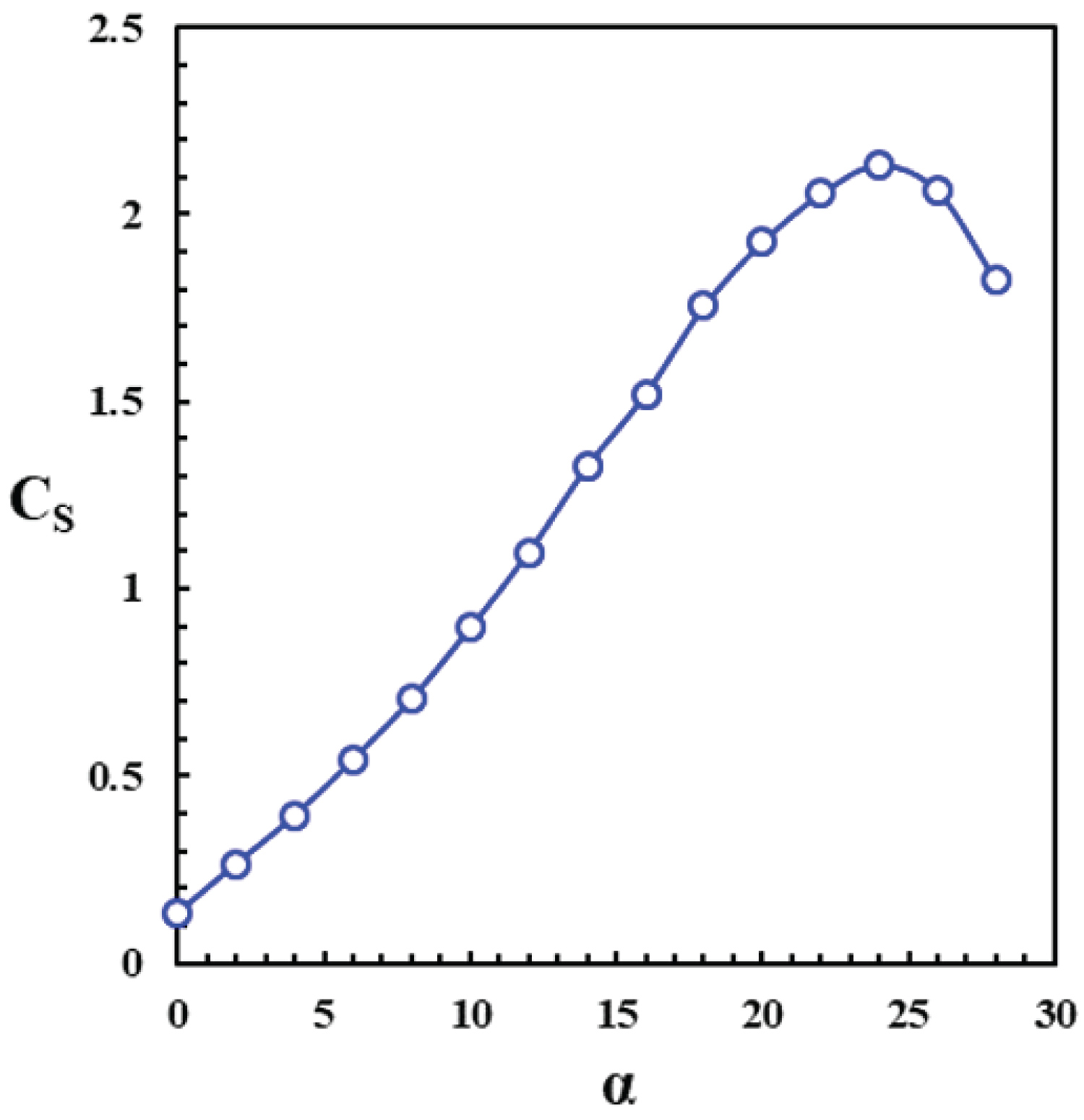
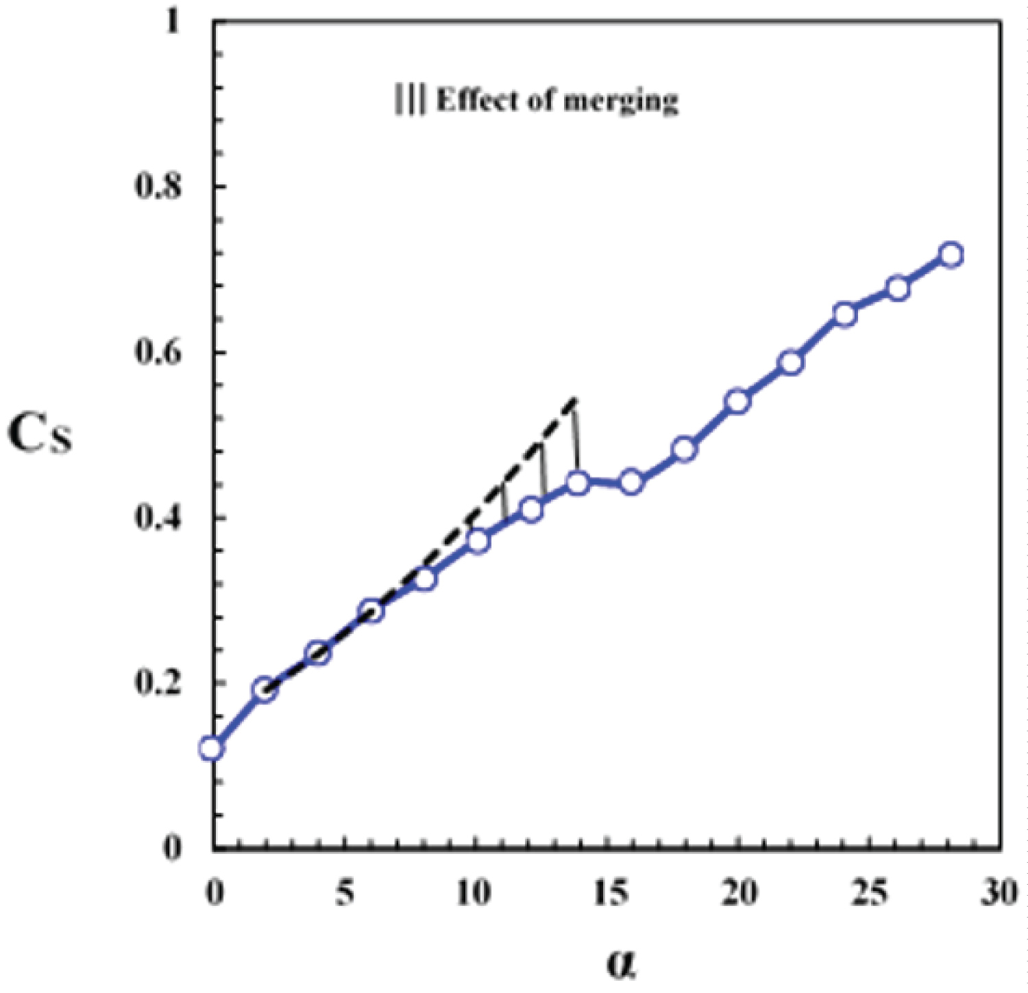
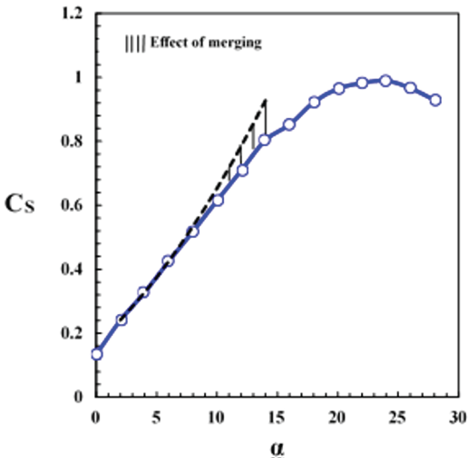
Figure 16 shows variations of the estimated suction force coefficient with angles-of-attack at station Y/C = 0. 22. The suction coefficient is seen to increase non-linearly with angles-of-attack. The inner vortex strength increases at 6 deg. angles-of-attack and as a result, the suction-curve slope increases nonlinearly. This section stalls at about 24 degrees angle-of-attack. Figure 17 shows variations of the suction force coefficient with angles-of-attack at station Y/C = 0.86. At two degrees angles-of-attack, the outer vortex is formed over the wing surface, and the suction force coefficient is seen to increase significantly. The rate of increase of the outer vortex strength at 4 deg. angle-of-attack is lower than that at an angle of 2 deg., therefore, the suction curve slope is seen to reduce as the angle-of-attack is increased from 2 to 4 degrees. As mentioned before, the vortices seem to merge beyond an angle-of-attack of about 10 deg., Figure 10, thus the slope of the suction coefficient curve decreases because the spanwise integral over the pressure distribution in the region where the two vortices are merged is smaller than the integral over the pressure distribution with two suction peaks in the region of two separate vortices, Figure 17. Therefore, as the vortices are merged, the nonlinearity in the aerodynamic coefficients is reduced. The suction coefficient increases with angle-of-attack as long as the vortices are not affected by the vortex breakdown. At 16 deg. angle-of-attack, vortex breakdown appears in the merged vortices and as a result the suction peak collapses and spreads in the spanwise direction. This leads to a sharp reduction in the suction curve slope and a plateau in the curved is created, Figure 17. As the angle-of-attack is further increased, the increased width of the suction peak due to the vortex breakdown that was previously observed in the pressure distribution, Figure 10, compensates for the reduction of the suction peak to keep the suction coefficient curve slope positive.
Figure 18 shows the suction coefficient as a function of angle-of-attack over the entire upper wing surface. As the outer vortex is formed at angle-of-attack equal to 2 degrees, the suction coefficient increases significantly. Beyond an angle-of-attack of about 10 deg., as the inner and outer vortices seem to merge, the nonlinearly in the suction curve slope is reduced. The reduction of suction curve slope from 14 to 16 deg. angle-of-attack, indicates that the vortex breakdown point might have reached the station Y/C = 0.86 at an angle-of-attack of 16 deg.
In addition to the mean surface pressure distribution study at various angles-of-attack, the root mean square (RMS) of the pressure fluctuations were examined to better correlate the vortex formation, vortex merging, and vortex breakdown at different Y/C locations over the wing surface. The pressure fluctuations were calculated from Eqation 1 and were converted to Cprms values, using Equation 2.
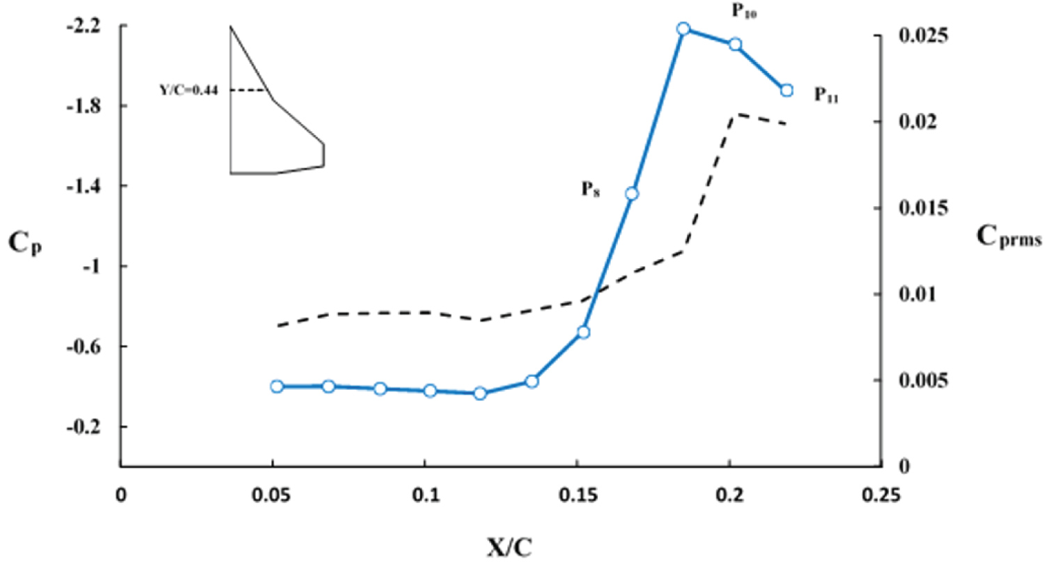
Where is the mean pressure at the point of measurement is, is the instantaneous pressure, and N is the number of samples. Note that for each pressure port, 106 ports, data at a sample rate of 1 KHz for 6 seconds, total of 6000 data points for each port, were collected. The spanwise pressure coefficient as well as its root mean square along station Y/C = 0.44 for an angle-of-attack of 14 deg. is shown in Figure 19. The left axis of the chart represents the surface pressure coefficient, Cp, and the right axis represents root mean square of the pressure coefficient, Cprms, the solid and dash lines are used for the values of the corresponding parameters, respectively. From this figure it is clearly seen that the maximum values of both │Cp│ and Cprms almost coincide with each other. Please note that the maximum value of Cprms could be used as an indication of the vortex core location.
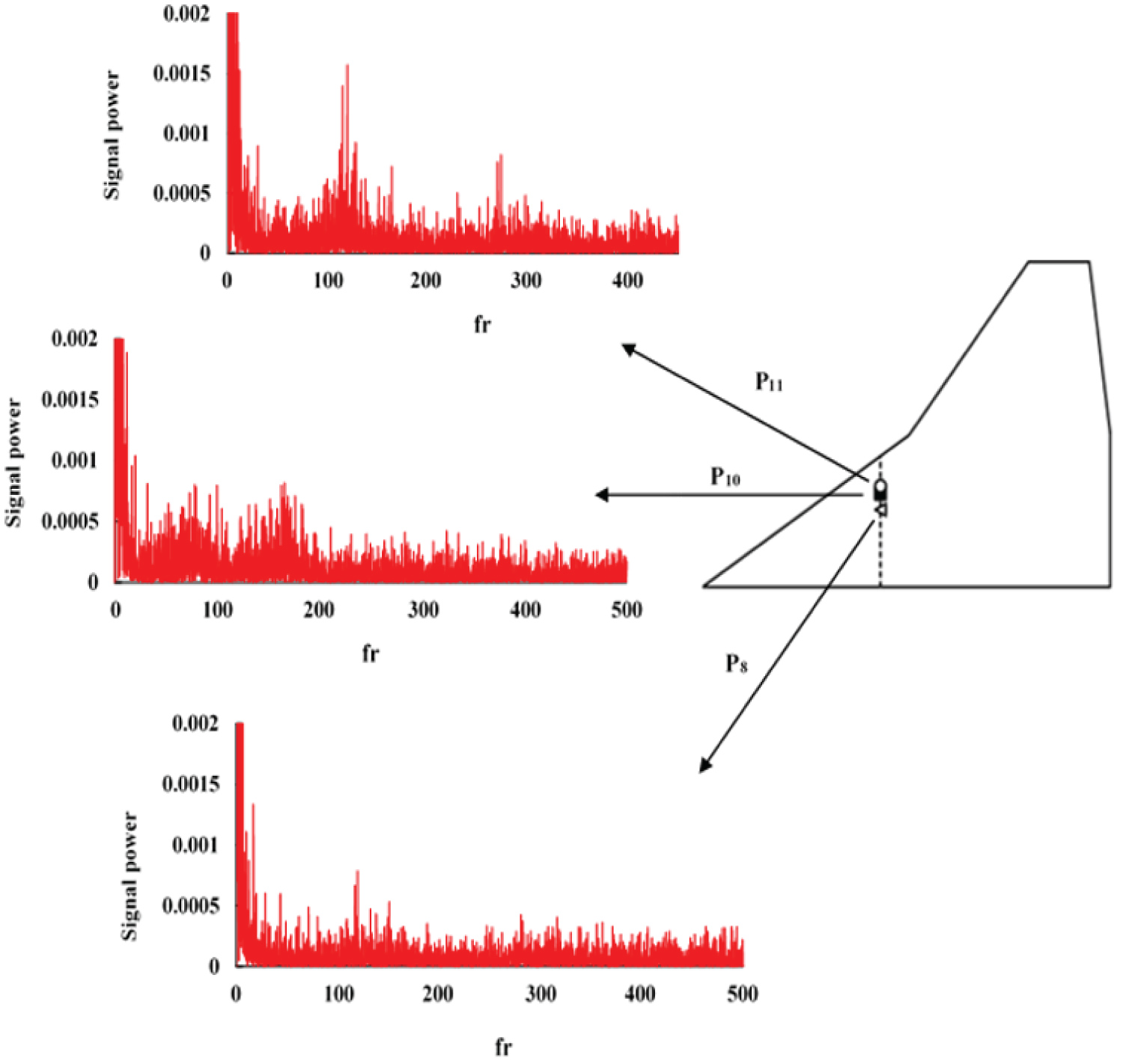
The power spectral densities of the surface pressure at three points along station Y/C = 0.44 are shown in Figure 20. The power spectra at a point P8 along the station Y/C = 0.44 has a single peak with a frequency of approximately 120 Hz while the power spectra for the point P10 shows a double-band frequency, Figure 20. The first band is centered at a frequency of approximately 80 Hz and the second one is centered at a frequency of approximately 160 Hz. Note that the location of the double-peak spectrum is very close to the suction peak, although slightly outboard of it, P10 in Figure 19 and Figure 20. It is interesting that a similar double-peak-type spectrum was obtained by Woods and Wood over a lambda wing [30]. Furthermore, when the spectra of point P8 is considered, a single peak occurs at a frequency midway between the two harmonic peaks, 120 Hz. At a location outboard of the double peak region, P11, a broadband centered at a frequency of approximately 120 Hz as well as a single peak at a frequency of approximately 270 Hz are seen from the power spectra shown in Figure 20.
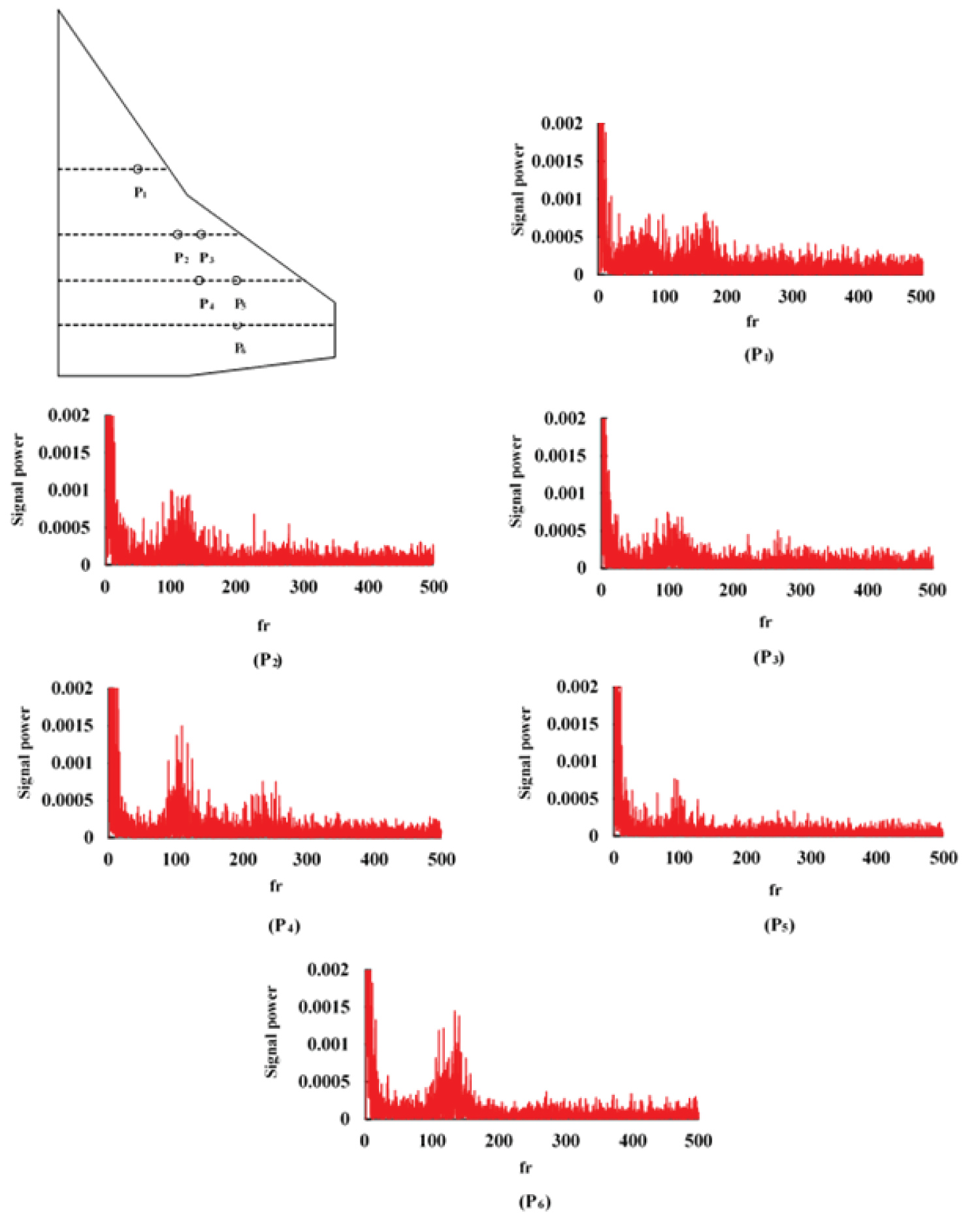
At an angle-of-attack of 14 deg., the power spectra of the pressure fluctuations at six points along four streamwise stations, corresponding to Y/C = 0.44, Y/C = 0.61, Y/C = 0.74, Y/C = 0.86 are shown in Figure 21. Note that these points are located in the regions of vortex cores with high Cprms values. These points and the angle-of-attack of 14 degrees were selected since they are located beneath the inboard vortex, outboard vortex, and the merged vortices. Moreover, for this angle-of-attack, 14 degrees, the surface pressure distribution does not indicate any sign of vortex breakdown for these pressure ports. As mentioned before, when the power spectra at point P1 of station Y/C = 0.44 is considered, two band of dominant peaks appeared in the power spectra that are centred at frequencies of approximately 80 Hz and 160 Hz and they seems to be harmonics, Figure 21, P1. The power spectra for point P2 which is in the region of the inner vortex core of station Y/C = 0.61 shows a broadband centered at a frequency of about 120 Hz. By approaching the outer vortex core at station Y/C = 0.61, point P3, a band with a dominant peak at a frequency of about 110 Hz is seen from the power spectra plot, Figure 21, P3. In addition, the magnitude of the power spectra for this point, P3, is seen to have been reduced considerably. A double-peak spectrum is observed at point P4 of the inner vortex at station Y/C = 0.74, and the peaks are centered at frequencies of approximately 110 Hz and 230 Hz. Again by moving outboard and approaching the outer vortex core at station Y/C = 0.74, point P5, there is a band at the lower center of frequencies of about 100 Hz and the reduced peaks which might be due to the weaker outer vortex, Figure 21, P5. At point P6 of station Y/C = 0.86 located underneath the core of the two merged vortices, a band of dominant peaks centered at about 120 Hz is clearly seen for this location. As the vortices move downstream, their size is increased and the interaction between them becomes stronger. Thus at station Y/C = 0.74, the two vortices interact with each other and finally at station Y/C = 0.86, the vortices merge at an angle-of-attack of 14 deg. Therefore, by comparing the power spectra at points P3, P5 and P6, it can be seen that as the vortices interact with each other and finally merge together to form a single vortex, the magnitude of the static pressure power spectrum increases and the frequency of the strongest vortex becomes the dominant one.
Conclusion
The vortex merging phenomena over a cranked-delta wing at subsonic speed was investigated via extensive surface pressure measurements. The vortices were indicated by two suction peaks in surface pressure distributions. The size and circulation of the vortices increased with angle-of-attack. As moving downstream at a constant angle-of-attack, the strength of the vortices were decreased and as a result the suction peaks in the downstream direction, toward the trailing edge are reduced. It was observed that the two vortices rotate in the same direction so they tend to move around each other. As one moves downstream, the vortices are widened and cover a large portion of the wing surface, and as a result, the interaction between them increases with increase in angle-of-attack. The results showed that the outer vortex was formed at an angle-of-attack of about 2 degrees which lead to a significant increase in the suction force coefficient. Above an angle-of-attack of 4 degrees, the variation of the suction force with angle-of-attack became nonlinear due to the increase in the strength of the inner vortex. The merging angle-of-attack, could be detected where the nonlinearly in the suction curve slope is reduced .The significant decrease in the suction force curve slope indicates that the vortex breakdown point might have reached the trailing edge at an angle-of-attack of about 16 deg. In addition , frequency analysis of the pressure data indicated that the frequency of the merged vortices is higher than those of the inner and the outer vortices due to the same direction of rotation.
References
- Elsayed M, Scarano F, Verhaagen NG (2007) Particle image velocimetry study of the flow over a slender delta wing. 25th AIAA applied aerodynamics conference, Miami, Florida, USA.
- Gursul I, Gordnier R, Visbal M (2005) Unsteady aerodynamics of nonslender delta wings. Progress in Aerospace Sciences 41: 515-557.
- Payne FM (1987) Structure of leading-edge vortex flows including breakdown. Ph.D. Dissertation, University of Notre-Dame, USA.
- Polhamus EC (1986) Vortex lift research: Early contributions and some current challenges. NASA Conference Publication 1: 1-30.
- Skow AM, Erickson GE (1982) Modern fighter aircraft design for high angle of attack maneuvering. AGARD-LS-11: 4-1-4-59.
- Soltani MR (1992) An experimental study of the relationship between forces and moments and vortex breakdown on a pitching delta wing. Ph.D. Thesis, University of Illinois at Urbana Champaign.
- Verhaagen NG, Elsayed M (2008) Effects of leading edge shape on the flow over 50-deg delta wings. 26th AIAA applied aerodynamics conference, Honolulu, Hawaii.
- Wentz WH, Kohlman DL (1971) Vortex breakdown on slender sharp-edged wings. J Aircraft 8: 156-161.
- Yayla S, Canopolat C, Sahin B (2013) The effect of angle of attack on the flow structure over the nonslender lambda wing. Aerosp Sci Technol 28: 417-430.
- Zhang M, Yang Y, Lu Zh, et al. (2011) Unsteady characteristics of breakdown vortices over delta wing. Applied Mechanics and Materials 66-68: 1874-1877.
- Brennenstuhl U, Hummel D (1982) Vortex formation over double-delta wings. ICAS-82-6.6.3, 1302-1309.
- Verhaagen NG (1983) An experimental investigation of the vortex flow over delta and double-delta wings at low speed. Delft University of Technology.
- Cunningham AM, Den Boer RG (1990) Low speed aerodynamics of a pitching straked wing at high incidence - Part II harmonic analysis. J Aircraft 27: 31-41.
- Dehghan Manshadi M, Eilbeigi M, Sobhani MK, et al. (2016) Experimental study of flow field distribution over a generic cranked double delta wing. Chinese J Aeronaut 29: 1196-1204.
- Gai SL, Roberts M, Barker A, et al. (2004) Vortex interaction and breakdown over double-delta wings. The Aeronautical Journal 108: 27-34.
- Hebbar SK, Platzer MF, Li FH (1993) A visualization study of the vortical ?ow over a double-delta wing in dynamic motion. 11th Applied Aerodynamics Conference, Monterey, CA, USA.
- Hebbar SK, Platzer MF, Alkhozam AM (1996) Experimental study of vortex ?ow control on double-deltawings using ?llets. J Aircraft 33: 743-751.
- Hebbar SK, Platzer MF, Chand WH (1997) Control of high-incidence vortical ?ow on double-delta wings undergoing sideslip. J Aircraft 34: 506-513.
- Hebbar SK, Platzer MF, Fritzelas AE (2000) Reynolds number effects on the vortical-flow structure generated by a double-delta wing. Experiments in Fluids 28: 206-216.
- Hoeijmakers HWM, Vaatstra W, Verhaagen NG (1983) Vortex flow over delta and double-delta wings. J Aircraft 20: 825-832.
- Kumar A, Kumar P, Das S, et al. (2017) Effect of leading edge shapes on 81°/45° double-delta wing at low speeds. Proc IMechE Part G: Journal of Aerospace Engineering 232: 3100-3107.
- Olsen P, Nelson R (1989) Vortex interaction over double-delta wings at high angles of attack. 7th Applied Aerodynamics Conference, Seattle,WA, USA.
- Rao BS, Kurade R, Sivaramakrishnan AE, et al. (2013) Experimental investigation of the flow over an 80°/45° rounded leading edge double-delta wing-body model. 51st AIAA Aerospace Sciences Meeting including the New Horizons Forum and Aerospace Exposition, Texas, USA.
- Thompson DH (1985) A visualization study of the vortex ?ow around double-delta wings. Defense Technical Information Center.
- Verhaagen NG (1995) A study of the vortex flow over 76/40 deg double-delta wing. 33rd Aerospace Sciences Meeting and Exhibit, Reno, NV, U.S.A.
- Verhaagen NG (2002) Effects of reynolds number on flow over 76/40-degree double-delta wings. J Aircraft 39: 1045-1052.
- Zhang X, Wang Z, Gursul I (2016) Interaction of multiple vortices over a double delta wing. Aerosp Sci Technol 48: 291-307.
- Diebold JM, Woodard BS, Monastero MC, et al. (2015) Experimental study of splitter plates for use with semispan wing models. AIAA SciTech 48: 291-307.
- Kline SJ, McClintok FA (1953) Describing uncertainties in single-sample experiments. The American Society of Mechanical Engineers 75: 3-8.
- Woods M, Wood N (2000) Aerodynamic characteristics of lambda wings. The Aeronautical Journal 104: 165-174.
Corresponding Author
Mohammad Reza Soltani, Professor, Department of Aerospace Engineering, Sharif University of technology, Tehran, I.R. Iran; Affiliate Professor, William E. Boeing Department of Aeronautics and Astronautics, University of Washington, Seattle, WA, USA
Copyright
© 2021 Zafarghandi FM, et al. This is an open-access article distributed under the terms of the Creative Commons Attribution License, which permits unrestricted use, distribution, and reproduction in any medium, provided the original author and source are credited.