Bioinspired Propulsion Design Concepts for Unmanned Aerial Vehicles (Drones)
Abstract
This study aimed to develop a propulsion design concept for smart drones (UAVs - Unmanned Aerial Vehicles) mimicking a bacterial flagellar motor that can be found in many bacterial cells. A preliminary propulsion design concept was developed based on using the conventional turbojet without the turbine to run the compressor following the flagellar motor organization. Design analysis through analytical and computations was carried out in terms of power/thrust generated as part of various design variables for the design concept considered. Results obtained with varying values of fan diameter and compression ratios indicated the feasibility of using the propulsion design for use in small drones and unmanned air vehicles. The developed concept was prototyped and found to be acceptable for overall integration. However, more detailed analysis, as well as experiments need to be conducted before application in industries.
Keywords
Propulsion, Bioinspired, Design analysis, Computational simulation, Power
Introduction
Unmanned-Air-Vehicles (UAVs), also referred as "drones" [1] represent an emerging technology not only in aerospace [2], but also in precision agriculture [3], firefighting [4], and traffic management [5] industries. Specific applications for UAVs include surveillance, reconnaissance, and search and rescue for both military and civilian sectors, monitoring and sensing and disaster management. The Defense Advanced Research Projects Agency (DARPA) has generally defined MAVs (Micro-Air-Vehicles) as having characteristic dimensions of 6 inches or less and being capable of flying at 25 mph for a duration of 30 minutes or more [6]. DARPA also defined Nano Air Vehicles (NAV) to be 3 inches, weigh 10 grams, and carry a payload of 2 grams. These MAV/NAV's may be also used as Unmanned-Air-Vehicles or small drones in several applications.
Several design concepts based on bird flapping mechanisms have been developed in the past [7-10] for small MAVs/drones. Shyy, et al. [11] reviewed the biological and aeronautical literature related to flapping flight. Raney and Slominski [12] investigated the mechanization and control concepts for biologically inspired MAV based on a hummingbird example. Luca, et al. [10] developed a novel morphing wing design for small drones for extended flight envelope applications. There are still several challenges to overcome in terms of weight, size and power consumption before UAV's are considered feasible and inexpensive for industrial applications. As UAV's develop, the need for more powerful, lower cost, propulsion devices will grow as well. Micro turbojets, such as the one produced by M-DOT Aerospace, are being further developed, and can be as small as 3" long producing slightly over one pound of thrust. There is a need to develop propulsion concepts for UAVs or drones for different industrial applications.
The objective of this study is to investigate a propulsion design concept for smart drones mimicking bacterial flagellar motor assembly. The design concept is based on using the conventional turbojet without the turbine to run the compressor. Design analysis through analytical and computations was carried out to estimate the performance characteristics. In addition, the design was rapid prototyped to further evaluate the assembly characteristics.
Inspiration from Bacterial Flagellar Motor
BFM Structure and Function
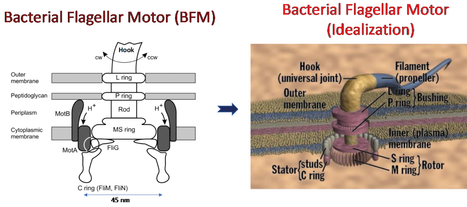
The Bacterial Flagellar Motor (BFM) is a rotary molecular motor found in many bacterial cells. A typical cell has 8 of these motors and each flagellum is driven by a reversible rotary motor embedded in the cell envelope. The motor powers the helical flagellar filaments rotation so that bacteria can swim towards a favorable location. The bacterial flagellum molecular structure has been investigated for many years [13-18]. The cell envelope in which the BFM is embedded encloses the cytoplasm and the two membranes are separated by the periplasm (about ~30 nm). The BFM components include basal body, hook and filament [14] as shown in Figure 1. The BFM's basal body has multiple ring structures (L ring, P ring, MS ring, and C ring). It spans the cellular envelope and is comprised of several transmembrane rings (approximately 50 nm in diameter which contain about 25 different proteins) that connect to the filament by a flexible hook. The major components involving the BFM rotation are the rotor and stator and their contact forces (see Figure 1 right). The stator is a ring (with discrete motor proteins) in the inner membrane and extends to anchor to the peptidoglycan layer. These stator motor proteins (MotA/B) consist of channels through which the proton- motive force pushes protons. The generated proton flux through this mechanism generates torque that drives the rotor rotation. The rotor is connected directly to a rod (an axial driveshaft) that transmits the torque across the periplasm to the flagellum via the hook (a short universal joint). The universal joint enables transmission of torque off-axis to the motor, and this is important because most bacteria have multiple flagella that must thrust coherently in the same direction for effective propulsion [13,14,16,17].
The BFM rotation occurs through the interaction between the torque-generating stator units and the rotor ring as shown in Figure 1 (right). Across the cellular membrane, this interaction is powered by the ion-motive force arising from the transit of ions (protons). The BFM converts the free energy stored in this transmembrane electrochemical gradient of ions H+, Na+, or K+ across the cytoplasmic membrane into mechanical work which is remarkable due to its ability to convert this free energy efficiently, operating close to 100% efficiency. The BFM operates close to 100% efficiency through its rotational speed of approximately 18000 rpm, and propels the bacteria at a speed up to 100 µm/sec which can output a power of approximately 1.5 × 10⁵ pN nm/sec [16,19]. The BFM generates torques of 4000 pNm near stall, and is the powerhouse of protein motors. The radius of the rotor is around 20 nm, and generates a force of 200 pN far greater than any other molecular motor.
As discussed in recent reviews [14,16,18,20] our understanding of the BFM has improved over the past several decades and demonstrates that the BFM is more complex than any man-made molecular machines. However, there remain several unknowns in terms of the BFM's atomic structure and its function. More research in terms of modeling, simulations and experiments is needed in the future to further investigate this remarkable nature inspired motor molecular structure and its function.
BFM versus Electric Motor
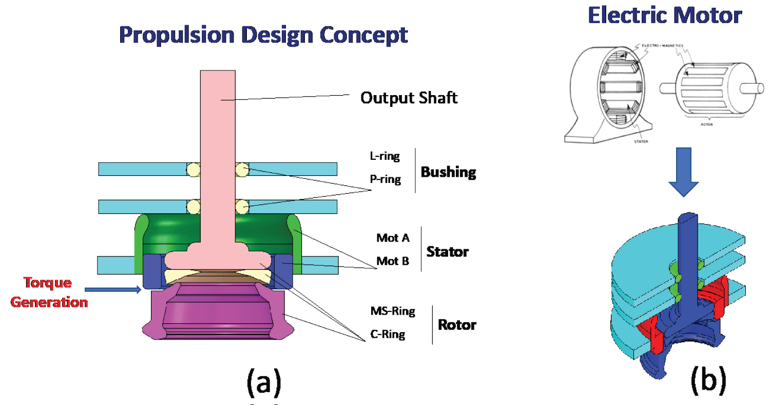
The general layout of the motor along with various components is presented in Figure 2. The components of this idealized concept includes stator, rotor, bushing and a shaft. The torque is generated between the stator and rotor (see Figure 2a). In order to achieve the power requirements of UAVs, a possible motor/pump concept inspired from biology is explored in this research investigation.
In terms of construction and function, the BFM can be compared to an electric motor as shown in Figure 2b. The MS-ring and C-ring (see Figure 1) make up the rotor or armature in an electric motor. The MotA and MotB rings make up the stator or windings in an AC motor. The L and P-rings act as bushing for the rotor shaft. The entire structure is supported by the cell inner and outer membranes. BFM draws its energy from a transmembrane electrochemical gradient of protons or sodium ions. The specific mechanisms and structures responsible for utilizing this energy are not completely known. The fuel for this motor could be as simple as ordinary table salt or hydrogen. To use a derivative of the flagellar motor to power a propulsion system for an UAV, the characteristic size is going to have to go from 20 nm to 20 mm, a scale up of 1,000,000. Obviously, a single protein cannot be scaled up one million times. Other materials will have to be substituted. One possibility is to mold the components from a polymer based material and coat it with a protein layer. The function of the BFM is based on protein interaction so that will have to be preserved in some manner. The characteristics of the motor are known on the bacterial scale, but how these values will scale up is still unknown. As the spindle speed and torque are important quantities for designing a propulsion system, but are not known, a preliminary design concept was developed and is discussed in the next section.
Turbineless Jet Engine Design Concept
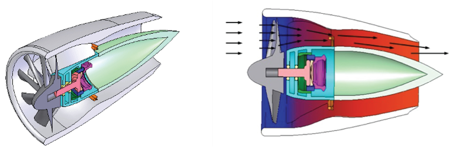
The design concept uses the conventional turbojet without the turbine, and a variation of BFM was used to run the compressor as shown in Figure 3. As in a conventional turbojet the compressor draws in oncoming air and forces it through a compression section. The compressed air is then mixed with fuel and ignited. The combustion adds more energy to the flow and the high velocity gases are directed out the rear of the engine through a nozzle.
A conventional turbojet engine uses the expanding gases of a combusting fuel/air mixture to power a turbine that drives a compressor. This system sustains itself while producing thrust. The turbojet and its derivatives such as the turbofan and turboprop have been used very successfully on full size aircraft and have been continually improved over the years to be very efficient methods of propulsion. By removing the turbine, the mechanism becomes much simpler. The turbine is often the biggest hurdle in jet engine design. Because of the high heat involved exotic materials and designs make the complexity and cost of jet engines very high. Because the turbine was used to power the compressor a motor must take its place. The turbine leaves the compressor as the only moving part remaining. Doing away with the turbine reduces the high tolerance machining and manufacturing involved with the turbine. To achieve good efficiencies the tip clearance of the blades and the walls has to be extremely close. The compressor is the only remaining component that requires a high level of precision. One approach to eliminate the turbine, is to replace it with a BFM style motor to drive the compressor. Also, the combustion can be replaced by a ceramic heater to add energy to the flow and create additional thrust, which is discussed later.
Design Analysis
Both analytical and computational analyses were carried out to evaluate the performance characteristics related to the proposed design concept (see Figure 4). The results obtained are presented below.
Analytical solutions
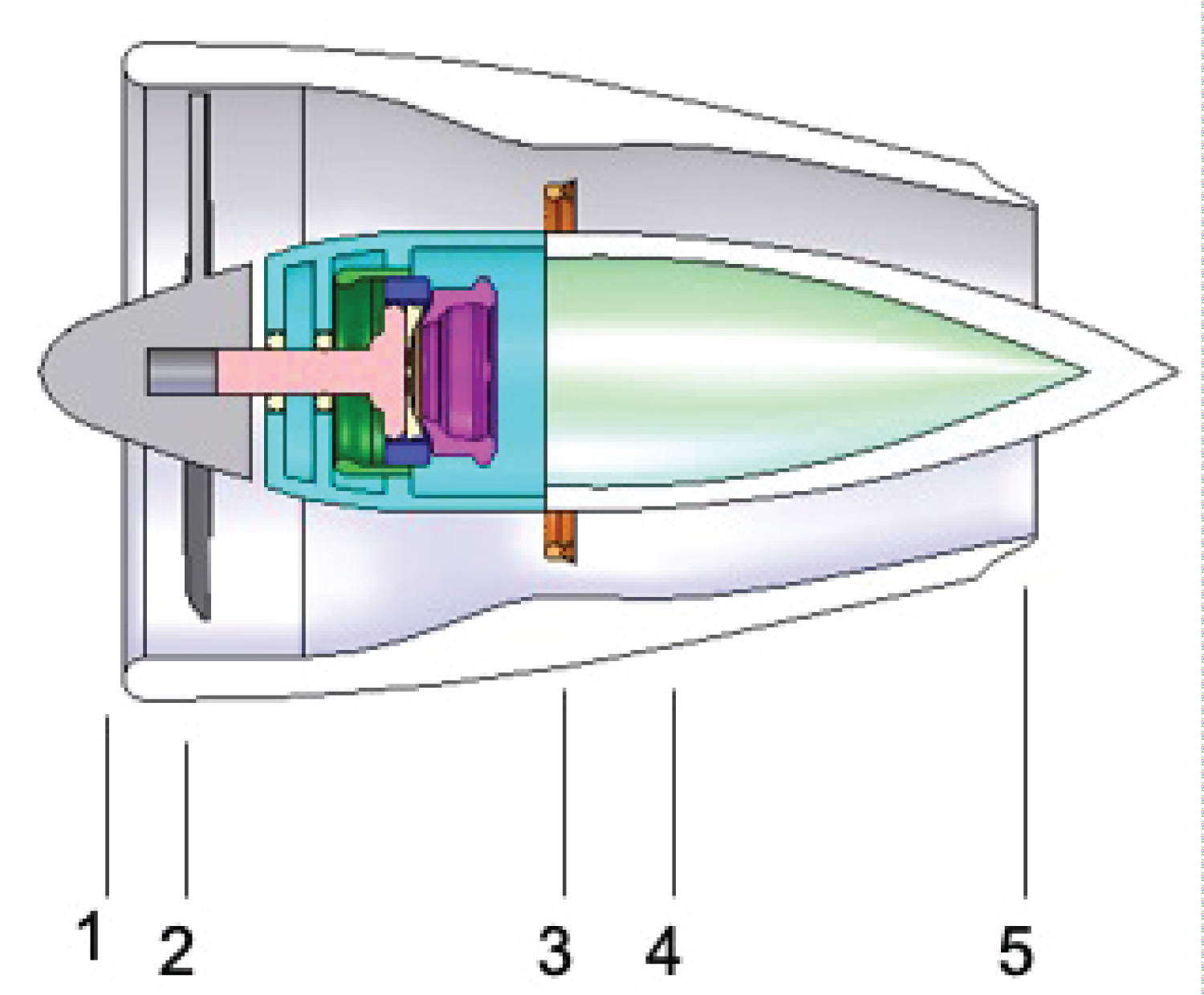
Equations were derived based on the turbojet equations for stagnation temperature and pressure at each stage of the engine. The engine is broken down into five stages at which the temperature and pressure are calculated. Because there is no turbine the engine discussed here only has four major regions to be analyzed. The engine breaks down into the following sections: inlet, compressor, burner, and the nozzle as shown in Figure 4.
Compressor (1-2) inlet conditions
The stagnation temperature, T02, at the compressor face is given by
where Ta is the ambient temperature, u is the freestream velocity, and a is the ambient speed of sound. γd is the specific heat ratio for the diffuser. The corresponding stagnation pressure can be evaluated with
where ηd is the adiabatic efficiency of the diffuser.
Compressor (2-3) outlet conditions
The compressor pressure ratio is given by the design of the engine and yields the compressor outlet stagnation pressure as
The compressor outlet stagnation temperature can then be found with
Where γc and ηc are the specific heat ratio and adiabatic efficiency for the compressor stage, respectively.
Burner (3-4) outlet conditions
The exhaust gas temperature, T04, is a design parameter that is specified. The burner pressure ratio is also specified and is typically slightly less than one making the burner a diffuser. The burner outlet pressure is thus given by
The fuel air mixture can be found given the fuel heating value, Qr, and specific heat, cp
Nozzle (4-5) exit velocity
The exhaust gas velocity can be found with
where R is gas constant, γn is the specific heat ratio for the nozzle, and ηn is the adiabatic efficiency for the nozzle.
Thrust
Given the exit velocity and the mass flow rate into the engine the thrust can found by
Analytical results and discussion
Based on the above analytical equations, several design analyses were carried out with varying parameters. The design parameters considered include the fan diameter, and the compressor ratio along with specific heat ratios and efficiencies. Table 1 shows the typical values for the specific heat ratios and efficiencies used to analyze the engine concept. Reasonable values for the design parameters were chosen to perform the analysis and obtain some thrust data. The parameters used are given in Table 2.
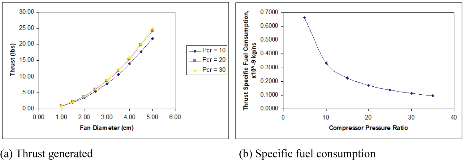
The results of thrust obtained as a function of the fan diameter are shown in Figure 5. It can be seen from Figure 5 that the thrust generated increases as the fan diameter is increased. The thrust also increases as the pressure ratio is increased. The compressor disc diameter was varied from 1cm diameter to 5 cm diameter. The compression ratio of the compressor had a slight effect on the resulting thrust but not substantial. When the fan diameter is increased from 2 to 4, the thrust increases by 300%. The specific fuel consumption as a function of compressor pressure ratio is shown in Figure 5b. It can be seen from Figure 4 that the compression ratio has a large effect on fuel consumption. When the compressor pressure ratio is increased from 5 to 20, the specific fuel consumption reduces by 100%.
The analytical study illustrated that a very small jet engine could produce more than an adequate amount of thrust to propel an MAV. It is clear that the compression ratio is not a large factor in thrust produced, but it is a large factor in the specific fuel consumption. To obtain a fuel friendly engine the compression ratio needs to be above 10.
CFD results and discussion
Preliminary CFD (Computational Fluid Dynamics) analysis was performed to examine the geometry of the ducting within the jet engine concept. FLOworks for SolidWorks was utilized to perform the analysis. FLOworks requires an enclosed computational domain so the geometry was modified slightly to meet this condition.
From the CFD analysis, the design now has a compression ratio of around 5. Fixing the compression ratio at a specific value at or above 10 will allow the geometry and the volume rate in air to be backsolved through CFD. Knowing the required incoming flow rate will lead to the required spindle speed and torque of the fan.
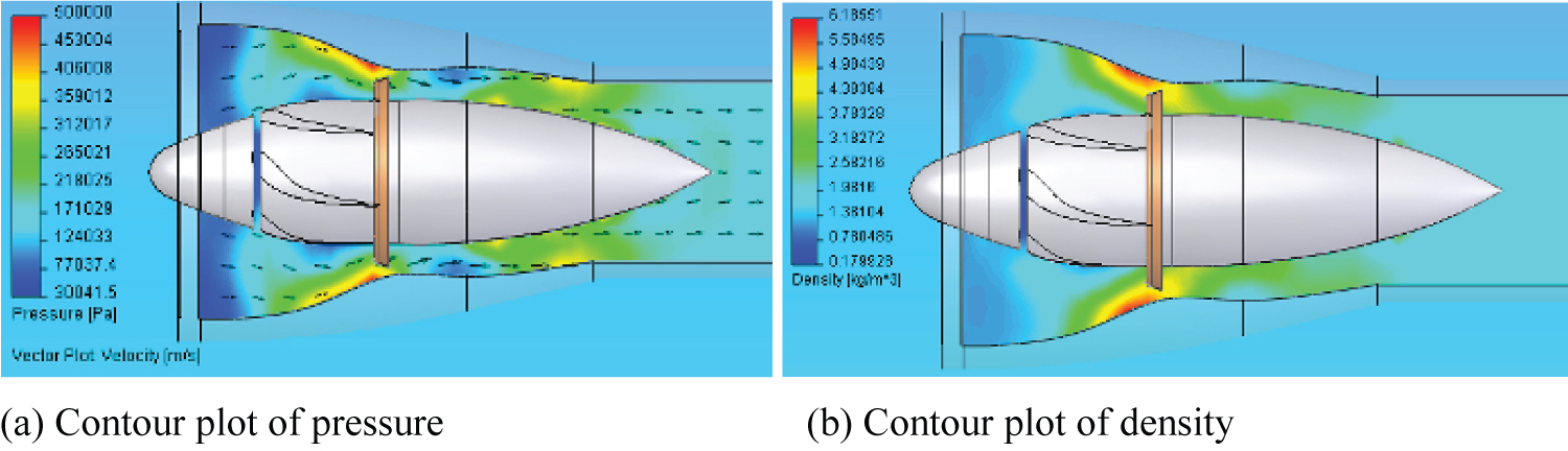
The results of pressure and density contours obtained from CFD analysis are presented in Figure 6. Based on the results, the maximum pressure is around 500 kPa. The resulting compression ratio is slightly under 5. The maximum pressure occurs on the outer wall at the injector ring. On the inside of the injector the pressure is considerably lower. A pressure gradient across the injector ring may be a desirable situation to induce mixing of the fuel and air. Modern jet engines use complex burner geometries with reversing flow to induce fuel/air mixing. In an engine this small, complex burner geometry would drive the cost up significantly. A compression ratio of 5 is quite low and will require a large amount of fuel to run for a length of time. As shown previously, a minimum compression ratio of 10 is desirable to maintain good fuel consumption.
Rapid prototyping
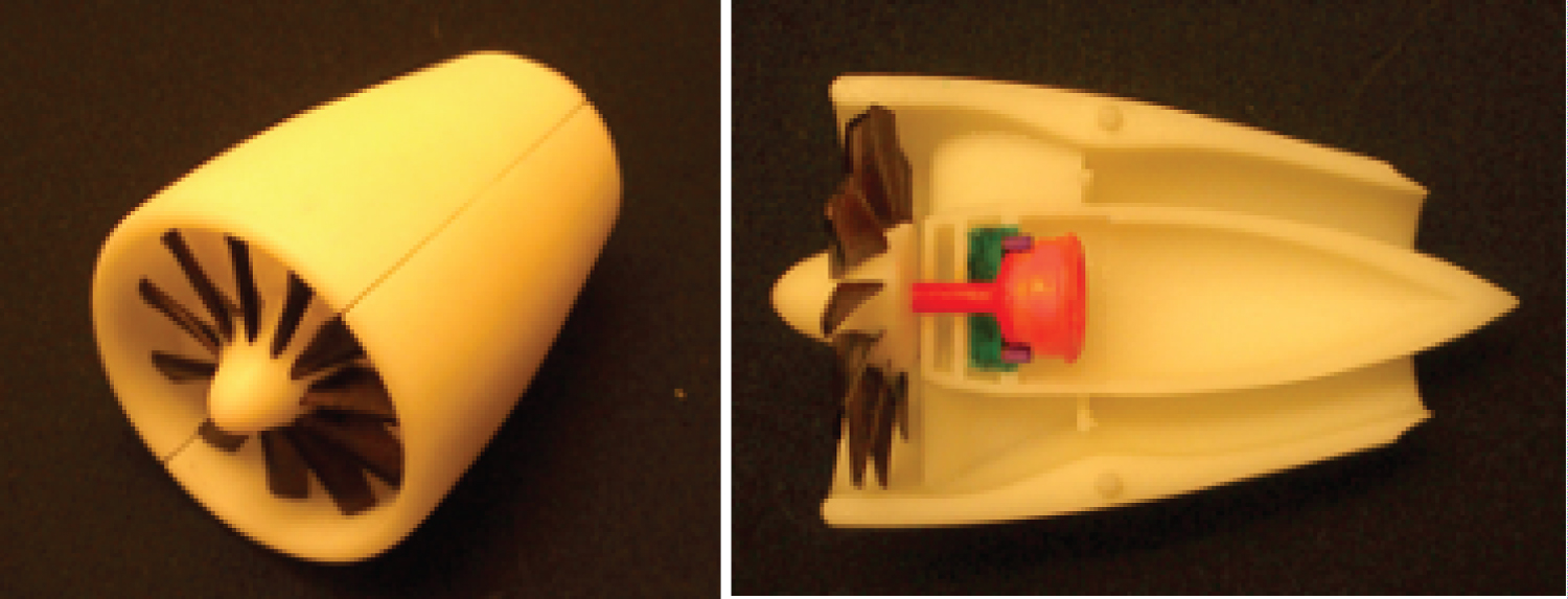
A three dimensional physical model was produced as shown in Figure 7 in the rapid prototyping facility at VCU. The machine used was a Viper Stereolithography machine by 3D Systems. The prototype was used to visualize the placement of the flagellar motor components and their function and overall assembly characteristics.
Realization of BFM with Electric Jet Propulsion
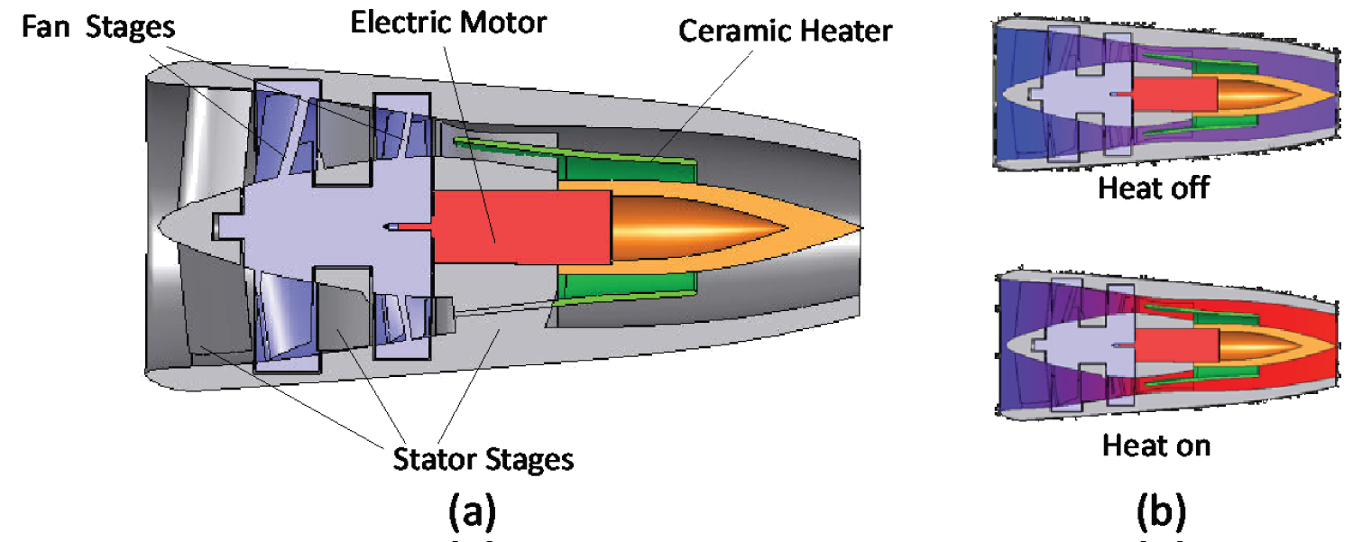
As discussed earlier, to reduce the complexity involved in working with conventional turbojets, the turbine will be replaced with a BFM style motor to drive the compressor. In addition, the combustion can be replaced by a ceramic heater to add energy to the flow and create additional thrust. To further demonstrate the feasibility of a turbineless jet engine propulsion for small drones, a novel concept for an 'electric jet' is proposed as shown in Figure 8 (left). The electric jet is similar to a conventional turbojet in that a compressor fan draws in oncoming air and forces it through a compression section. In order to achieve enough energy to generate required thrust, conventional turbojets use combustion to create heat and add energy to the incoming flow. In our proposed design concept, a ceramic heater can be used to create the required energy for thrust generation. Using an electric heater rather than combustion eliminates this need and simplifies the design all around by reducing the compression ratio required and eliminating complex burner geometry required by conventional gas turbines to properly mix the fuel and maintain combustion. Conventional turbojets use a turbine to drive the compressor off the combusted gases. The electric jet will have no turbine and will use an electric or other type of motor to drive the compressor. Figure 8 shows the general concept and the various components.
A single or dual stage axial compressor draws in air and compresses it through ducting. The compressed air is then heated as it passes over multiple ceramic heaters in the aft section of the engine. The heated air expands and is ejected out the nozzle of the engine producing thrust (Figure 8 (right)). Since the compressor is driven independently the engine could function as a ducted fan by not activating the heater. This mode will save valuable power. The heater could be used similar to an afterburner and activated when more thrust is required. Potential benefits include lower cost, ease of manufacturing, improved performance and efficiency and applicability to many small UAVs/drones. These aspects need to be investigated in the future.
Concluding Remarks
A preliminary propulsion concept based on bacterial flagellar motor was developed for use in smart drones. The design concept uses the conventional turbojet without the turbine, and a variation of BFM was used to run the compressor. Design analysis was carried out in terms of analytical power/thrust generated, computational fluid dynamics, and rapid prototyping. Results indicated that the design concept is a feasible idea for use in smart drones/UAV's. However, more detailed analysis, as well as experiments need to be conducted before application in drones.
Acknowledgments
The research described in this paper was supported by the VCU startup funds.
References
- Schneider D (2014) Open season on drones? IEEE Spectr 51: 32-33.
- Ogan R (2014) Integration of manned and unmanned aircraft systems into U.S. airspace. Proceedings of the IEEE SOUTHEASTCON 2014, Lexington, KY, USA.
- Valente JA, Sanz D, Barrientos A, et al. (2011) An air-ground wireless sensor network for crop monitoring. Sensors 11: 6088-6108.
- Chen M, Hu Q, Mackin C, et al. (2015) Safe platooning of unmanned aerial vehicles via reachability. 54th IEEE Conference on Decision and Control (CDC), Osaka, Japan, 4695-4701.
- Giyenko A, Cho YI (2016) Intelligent unmanned aerial vehicle platform for smart cities. 2016 Joint 8th International Conference on Soft Computing and Intelligent Systems (SCIS) and 17th International Symposium on Advanced Intelligent Systems (ISIS), Sapporo, Japan, 729-733.
- Miller TL (2000) Proceedings of the conference on fixed, flapping and rotary wing vehicles at very low reynolds numbers. Department of Aerospace and Mechanical Engineering, University of Notre Dame, Indiana.
- Grasmeyer JM, Keennon MT (2000) Development of the black widow micro air vehicle. AIAA Paper 2001-0127.
- Ifju PG, Jenkins DA, Ettinger S, et al. (2002) Flexible wing-based micro air vehicles. AIAA Paper 2002-0705.
- Morris S, Holden M (2000) Design of micro air vehicles and flight test validation. Proceedings of the Conference on Fixed, Flapping and Rotary Wing Vehicles at Very Low Reynolds Numbers, Department of Aerospace and Mechanical Engineering, University of Notre Dame, Indiana.
- Luca MD, Mintchev S, Heitz G, et al. (2017) Bioinspired morphing wings for extended flight envelope and roll control of small drones. The Royal Society Interface Focus 7.
- Shyy W, Berg M, Ljungqvist D (1999) Flapping and flexible wings for biological and micro vehicles. Progress in Aerospace Sciences 35: 455-506.
- Raney DL, Slominski EC (2004) Mechanization and control concepts for biologically inspired micro air vehicles. Journal of Aircraft 41: 1257-1265.
- Sowa Y, Richard MB (2008) Bacterial flagellar motor. Quarterly Reviews of Biophysics 41: 103-132.
- Nakamura S, Minamino T (2019) Flagella-driven motility of bacteria. Biomolecules 9: 279.
- Kitao A, Hata H (2018) Molecular dynamics simulation of bacterial flagella. Biophysics Reviews 10: 617-629.
- Nirody JA, Yi-Ren Sun, Chien-Jung Lo (2017) The biophysicist's guide to the bacterial flagellar motor. Advances in Physics 2: 324-343.
- Mora T, Yu Howard, Sowa Y, et al. (2009) Steps in the bacterial flagellar motor. PLOS Computational Biology 5.
- Berg H (2003) The rotary motor of bacterial flagella. Annul Reviews of Biochemistry 72: 19-54.
- Xue R, Ma Q, Matthew AB Baker, et al. (2015) A delicate nanoscale motor made by the nature - the bacterial flagellar motor. Advanced Science 2: 1500129.
- Beeby Morgan (2018) The bacterial flagellar motor and the evolution of molecular machines. Biochem (Lond) 40: 4-9.
Corresponding Author
Ramana M Pidaparti, College of Engineering, University of Georgia, Athens, GA 30602, USA; Evan B Neblett, Research Engineer, Newport News Shipbuilding, Newport News, Virginia, USA.
Copyright
© 2021 Pidaparti RM, et al. This is an open-access article distributed under the terms of the Creative Commons Attribution License, which permits unrestricted use, distribution, and reproduction in any medium, provided the original author and source are credited.