Bonded Tri-Material Specimen Subjected to Shear-Off Testing: Predicted Interfacial Stresses
Abstract
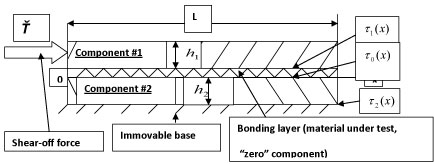
A physically meaningful and easy-to-use analytical model based on the concept of the interfacial compliance is developed for the evaluation of the interfacial shearing stresses at failure from the measured shear off force. The level of these stresses characterizes the adhesive strength of the bonding material of interest. A tri-material test specimen rigidly attached to an ideally strong immovable base is considered. The shear-off force is applied to its upper ("free") component. It is assumed that the shear-off mechanical stresses are significantly higher than the residual thermally induced stresses, and therefore the latter do not have to be considered. The objective of the analysis is to determine the interfacial strength of the bonding material. It is shown that the distributions of the shearing stresses at the interfaces of this material with the bonded components mimic the shearing stress at the immovable base. The general concept is illustrated by a numerical example carried out for electronic silicon-copper assembly bonded using sintered silver. In this example the predicted stresses are higher at the interface of the bonding material with the upper, "free", component than at its interface with the component attached to the immovable base. The suggested model can be used when there is an intent to select, during product development testing, the most feasible bonding material from the standpoint of its interfacial strength. Future work should include, first of all, experimental data and finite-element confirmation of the analytical suggested analytical model.
Introduction
The objective of the analysis that follows is to develop a simple, physically meaningful and easy-to-use analytical model for the prediction of stresses from the measured shear-off force. This is a typical product-development test in microelectronic packaging engineering (see, e.g., [1,2]). The model is based on the concept of the interfacial compliance. This concept was first applied in [3] and recently addressed in detail in [4]. The numerical example is carried out for the case of a sintered silver bond [5-14]. Sintered silver is, as is known, a good candidate for die bonding as an alternative to lead alloys. Little is known, however, about its mechanical properties, and shear off testing can shed important light on the macroscopic characteristics of this material and, first of all, on its bonding strength. It should be emphasized that actual experimentation, which is considered as future work, should be based on the data obtained on the basis of the suggested analytical model. It is desirable; of course, that the data obtained using the developed model is confirmed by finite-element-analysis (FEA). Another point that should be made in connection with the suggested model and the numerical analysis below is that the suggested tri-material body considers that the axial compliance of the adhesive layer (zero component in Figure 1) does not have to be by orders of magnitude larger than the axial compliances of the two other components (in our numerical analysis this compliance is about 7-9 times larger than the compliances of the two other components). This means that the suggested model can be used to decide if a simplified bi-material model (of the type suggested in Ref.3 in application to thermal stresses) could be used in the addressed problem.
Analysis
The distributed longitudinal force T(x) acting in the cross-sections of the tri-material test-specimen (assembly) in Figure 1 can be sought in the form
where k is the parameter of the sought shearing stress. This parameter is loading independent and, for a stiff enough assembly that does not experience bending deformation can be evaluated as follows [15].
where the following notation is used:
, , , , , , , , , , , (3)
The partial parameters k01 and k02 refer to bi-material assemblies comprised of "zero" (bonding) and #1 components or of "zero" and #2 components; λ0, λ1 and λ2 are axial compliances of the assembly components; к0, к1 and к2 are their interfacial compliances; G0, G1 and G2 are the shear moduli of the component materials; E0, E1 and E2 are their Young's moduli; v0 and v1 are their Poisson's ratios; and δ is the parameter that characterizes the role of the relative axial compliances of the assembly components: when the "zero" component is considerably more compliant than the two outer components, this parameter is equal to 1. If all the three components have the same axial compliance, this parameter is equal to 0.25. When the "zero" component is very stiff, this parameter is zero.
The shearing stress τ2(x) can be found from (1) by differentiation:
For large enough values one can put . It is clear also that the shearing stress is zero for cross-sections remote from the left end of the assembly, where the force Ť is applied. Then the equation (2) yields: C1 = -C2, and the formulas (1) and (2) result in the following relationships for the total axial force acting in the assembly cross-sections and for the corresponding shearing stress:
,
The force T(x) should satisfy the boundary conditions:
,
Then the expression (1) results in the following equations for the constants C0 and C1:
,
so that
,
and
,
The maximum shearing stress takes place at the origin:
This stress changes from infinity to -kŤ, when the length L of the specimen changes from zero to a large enough value.
Let us determine now the shearing stresses acting at other interfaces of the assembly.
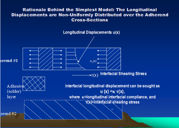
The longitudinal interfacial displacements can be sought, in accordance with the concept of the interfacial compliance [3], as
,
,
Where u01(x) is the displacement of the "zero" component at its interface with the component #1; u10(x) is the displacement of the component #1 at its interface with the "zero" component; u20(x) is the displacement of the "zero" component at its interface with the component #2; u20(x) is the displacement of the component #2 at its interface with the "zero" component; T0(x), T1(x) and T2(x) are the forces acting in the cross-sections of the assembly components; τ0(x) is the shearing stress acting at the interface of the "zero" component with the component #2; τ1(x) is the shearing stress acting at the interface of the "zero" component with the component #1; is the interfacial compliance of the "zero" component; is the interfacial compliance of the component #1; is the interfacial compliance of the component #2 (the formulas for the interfacial compliances are obtained based on the Ribière solution for a long-and-narrow strip [3,16] loaded over its long sides the way that the components in question are); , and are the shear moduli of the assembly component materials; E0, E1 and E2 are their Young's moduli; v0, v1 and v2 are their Poisson's ratios; h0, h1 and h2 are the component thicknesses; , and are the axial compliances of the components. These formulas consider the two-dimensional state of stress.
The first terms in the formulas (9) are based on the Hooke's law and reflect an assumption that the longitudinal (axial) displacements are uniformly distributed over the cross-sections of the given assembly component. The second terms are corrections to this assumption. They consider that the interfacial displacements are somewhat larger than the displacements of the inner points of the cross-sections (Figure 2).
The structure of these terms reflects an assumption that the corrections of interest can be sought as products of the stress-independent interfacial compliances and thus far unknown interfacial shearing stresses acting in this cross-section.
The conditions u01(x) = u10(x) and u20(x) = u20(x) of the displacement compatibility result in the equations:
Obviously,
Then the equations (10) results in following system of equations:
The equations of equilibrium require that
,
and therefore
, (14)
Then the equations (12) yield:
(15)
As one could see from the second formula in (7), . Assuming that a similar relationship holds for the sought shearing stresses τ0(x) and τ1(x) the following system of algebraic equations for the shearing stress functions τ0(x) and τ1(x) could be obtained:
(16)
These equations have the following solutions:
(17)
(18)
Here some of the notations (3) were used. As one could see from the solutions (17) and (18), all the interfacial stresses have similar distributions, only their ordinates are, of course, different.
Numerical Example
Input data
|
Structural element |
#1 (silicon) |
#2 (copper) |
0 (bond) |
|
Thickness, mm |
0.5 |
1.0 |
0.20 |
|
Young’s modulus, kg/mm2 |
19500 |
12000 |
6000 |
|
Poisson’s ratio |
0.24 |
0.32 |
0.35 |
|
Shear modulus, kg/mm2 |
7863 |
4545 |
2222 |
|
Assembly length, L = 10.0 mm; Measured shear-off force, Ť = 1.0 kg/mm |
|||
Calculated data
Axial compliances:
Copper (Component #2)
Adhesive ("zero" component)
Interfacial compliances:
Silicon (Component #1)
Copper (Component #2)
Adhesive ("Zero" component)
Partial parameters of the interfacial shearing stress:
Parameter of the relative axial compliances:
Parameter of the interfacial shearing stresses:
ratio:
ratio:
Thus, the shearing stresses at the bonding layer ("zero" component) interface with the lower component (component #2) are about 20.5% of the distributed shearing stresses at the interface of the component #2 with an immovable base, and the shearing stresses at the interface of the bonding layer with the upper component (component #1) are about 30% of the distributed shearing stresses of the of the component #2 with an immovable base.
With the measured shearing off force per unit assembly width of Ť = 1.0 kg/mm the maximum shearing stress at the left end of the test specimen at its interface with the immovable base is
The maximum stress in the bonding material is
at its interface with the lower component (component #2) and is
at its interface with the upper component (component #1).
Conclusion
A simple, easy-to-use and physically meaningful methodology has been developed for the evaluation of the interfacial stresses in a tri-material bonded test specimen from the measured shear-off force. Future work should include FEA, but, most importantly, experimental investigations based on the developed analytical technique.
References
- E Suhir (2002) Accelerated life testing (ALT) in microelectronics and photonics: Its role, attributes, challenges, pitfalls, and interaction with qualification tests. J Electr Packaging 124: 281-291.
- E Suhir (2013) Failure-oriented-accelerated-testing (FOAT) and its role in making a viable IC package into a reliable product. Circuits Assembly.
- E Suhir (1986) Stresses in bi-metal thermostats. J Appl Mech 53: 657-660.
- E Suhir (2018) Analytical thermal stress modeling in electronics and photonics engineering: Application of the concept of interfacial compliance. Journal of Thermal Stresses 42: 29-48.
- R Amro, J Lutz, J Rudzki, et al. (2006) Power cycling at high temperature swings of modules with low temperature joining technique, IEEE International Symposium on Power Semiconductor Devices & IC's, Naples, Italy.
- X Li, X Chen, DJ Yu, et al. (2010) Study on adhesive reliability of low-temperature sintered high power LED modules. 11th International Conference on Electronic Packaging Techn Technology & High Density Packaging, Xi'an, China.
- W Schmitt, WC Heraeus Gmbh (2010) Novel silver contact paste lead free solution for die attach. 6th International Conference in Integrated Power Electronic Systems, Nuremberg, Germany.
- M Knoerr, S Kraft, A Schletz (2010) Reliability assessment of sintered nano-silver die attach for power semiconductors. 12th Electronics Packaging Technology Conference, Singapore.
- J Kähler, N Heuck, A Wagner, et al. (2012) Sintering of copper particles for die attach. IEEE Transactions on Components, Packaging and Manufacturing Technology 2: 1587-1591.
- KS Siow (2012) Mechanical properties of nano-ag as die attach materials. J Alloys Compounds 514: 6-19.
- V Caccuri, X Milhet, P Gadaud, et al. (2014) Mechanical properties of sintered ag as a new material for die bonding: influence of the density. Journal of Electronic Materials 43: 4510-4514.
- KS Siow (2014) Are sintered silver joints ready for use as interconnect material in microelectronic packaging? J Electron Mater 43: 947-961.
- M Li, Y Xiao, Z Zhang, et al. (2015) Bi-modal sintered silver nanoparticle paste with ultra-high thermal conductivity and shear strength for high temperature thermal interface material applications. ACS Applied Materials and Interfaces 7: 9157-9168.
- KS Siow, ST Chua, ZA Samah (2018) Interfacial TEM analysis of sintered silver in air and N2 -5%H2 gases environment. 38-th Int. Electronic Manufacturing Technology Conf, Malacca, Malaysia.
- E Suhir (2001) Analysis of interfacial thermal stresses in a tri-material assembly. J Appl Physics 89.
- E Suhir (1991) Structural analysis in microelectronic and fiber optic systems. Volume I Basic principles of engineering elasticity and fundamentals of structural analysis. Van Nostrand Reinhold, New York, USA.
Corresponding Author
E Suhir, Departments of Mechanical and Material and Electronic and Computer Engineering, Portland State University, Portland, OR, USA; Department of Applied Electronic Materials, Institute of Sensors and Actuators, Technical University, Vienna, Austria; ERS Co., 727, Alvina Ct., Los Altos, CA 94024, USA.
Copyright
© 2020 Suhir E. This is an open-access article distributed under the terms of the Creative Commons Attribution License, which permits unrestricted use, distribution, and reproduction in any medium, provided the original author and source are credited.