Design and CFD Analysis of a Blended Wing UAV (A Conceptual Design)
Abstract
Aerodynamic Forces mainly lift and Drag acting on an aircraft, are directly related to the geometry and wing profile of an aircraft. In this research we first designed a blended wing UAV (using X48B as a baseline model) and then performed the CFD analysis. Focusing on the lift to drag ratio in Cruise conditions, we made changes to our initial design based on critical pressure regions found by simulation and afterwards improved our design to almost three times by making changes to the initial geometry.
Keywords
CFD, Blended wing, Simulation, FLUENT, GAMBIT, Meshing
Introduction
A Blended Wing Body has wings merged into the main body which gives it advantage over conventional aircrafts. Whole body acts as a wing that contributes to lift generation resulting in much higher lift to drag ratio and ultimately greater range and fuel efficiency.
One of the economical and efficient methods to calculate lift and drag coefficients nowadays is by using CFD software, which has both financial and technical advantages over conventional methods such as wind tunnel testing.
CFD Analysis is a stepwise simulation process starting with pre-processing. In pre-processing I first made CAD model, generated mesh and then defined boundary conditions for the problem. It is followed by second step know as processing or solution of the problem defined in first step. Finally the third step post processing of the results was carried out and conclusion was made.
The main objective of this research was to find the airflow patterns around the body and identify the critical regions based on pressure contours that were contributing to the drag force and then improve the design, get a maximum value for L/D ratio, compare it with general values for blended wing UAVs and see whether the design is suitable for manufacturing.
Literature Review
Air molecules slides over the skin of aircraft as it moves forward. The closest molecules to the skin act as if they are moving along with aircraft. If the air molecules closest to the aircraft skin are moving with it, there must be slippage (or "shear") between these molecules and the nonmoving molecules away from the aircraft. "Viscosity" is the honey-like tendency of air to resist shear deformation, which causes additional air near the aircraft skin to be dragged along with the aircraft. The force required to accelerate this "boundary-layer" air in the direction the aircraft is travelling produces skin-friction drag [1]. The skin friction associated with a turbulent boundary layer on a smooth surface decreases with increase of Reynolds number [2]. The drag on any aerodynamic body is composed of pressure drag and skin friction drag [3]. The large pressure drag of blunt bodies is due to the massive regions of flow separation [3].
No matter how complex the body shape may be, the aerodynamic forces and moments on the body are due entirely to the above two basic sources. The only mechanisms nature has for communicating a force to a body moving through a fluid are pressure and shear stress distributions on the body surface [3]. CFD is a catch-all phrase for a number of new computational techniques for aerodynamic analysis. It differs from prior aerodynamic codes by solving for the complete properties of the flow field around the aircraft, rather than only on the surface of the aircraft [1-9].
CAD Modeling, Flow Field Formation and Meshing
Geometry formation
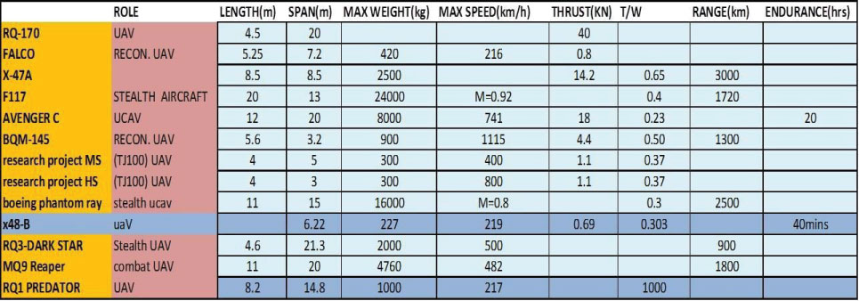
It is first step in CFD process. Mostly modeling of simple geometries and flow field is made using GAMBIT software. However for a complex geometry we need powerful CAD software such as pro-E or Solid works etc. So, a number of aircraft models were studied before starting the design as shown in Figure 1 below and then initial design was made and was improved using pro-E and SOLIDWORKS, and then it was imported in GAMBIT where flow field for the problem was made
Characteristics of design
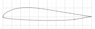
• Symmetric airfoil NACA 64a008 was selected at root chord to accommodate engine and other integral parts.
• For outboard wing, Eppler 342 was selected because it is specifically designed for tailless aircrafts and it possesses extremely low drag characteristics. Aspect ratio was of this airfoil was variable at different sections of the wing to have a minimum frontal area.
• Vertical section was added at wing to provide yaw stability.
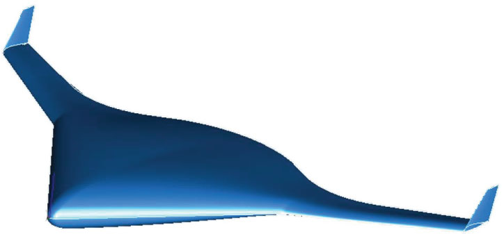
CAD model
(Figure 2 and Figure 3).
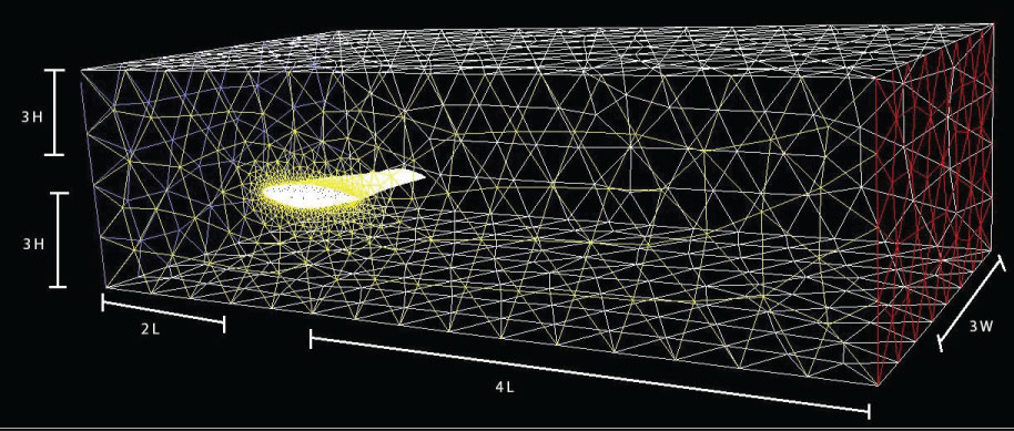
Flow field size
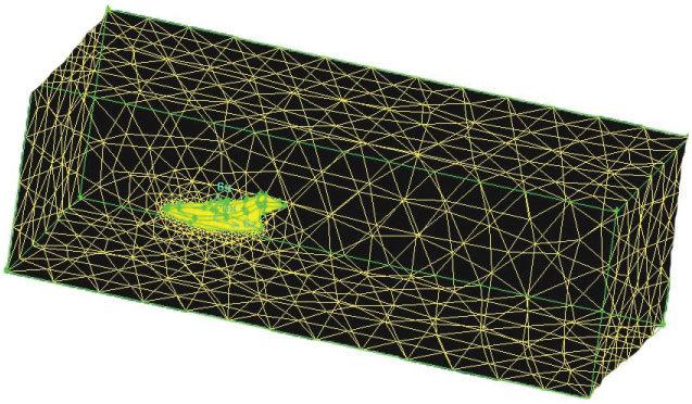
Size of flow filed for the problem was selected relative to the size of our design. The dimensions were as following where L, W and H represent the length, width and height of our design respectively (Figure 4).
Meshing
Next step after making flow filed was meshing. GAMBIT was used for meshing and tetrahedral volumetric mesh was created in the flow filed. Different mesh sizes were used for different zones and after mesh generation mesh quality was checked in terms of equisize skew. Zero value represents best element and one equisize skew represents worst. In our case, the worst element came out to be 0.83 which is OK because FLUENT can solve skewness up to 0.97 (Figure 5).
Boundary conditions
Fluid Continuum was selected because we were dealing with airflow. Inlet, outlet and symmetric planes were defined and finally a mesh file was created for solver FLUENT 6.
Simulations
As mentioned earlier, FLUENT software was used to carry out simulation. 3D Unsteady solver for incompressible flow was selected, inlet velocity of 70 m/s was defined and simulation was carried out for atmospheric pressure. Velocity and Pressure Contours were found and Values for Coefficients of Lift and Drag were plotted against iterations until the solution converged.
Results
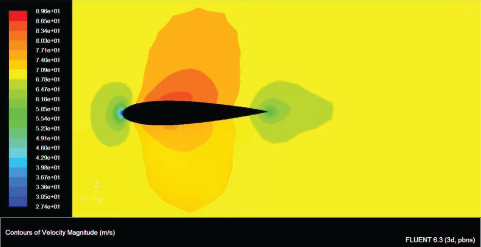
Velocity contours
Figure 6 shows velocity distribution over symmetric plane and can see that the distribution pattern was similar to any other aircraft.
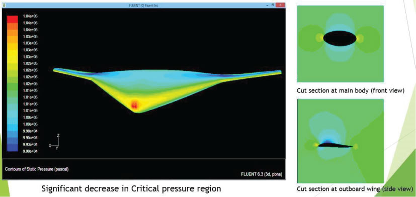
Pressure contours
Our main focus was on pressure distribution, because pressure acting on the surface contributes to drag force. Then we calculated the coefficients of lift and drag for our model and identified the critical regions in terms of maximum pressure that contributed to a higher drag value. Figure 7 shows pressure distribution on the body and 2 cut sections on main body and outboard wing. Red color indicates the critical region where we had maximum pressure.
Comparison
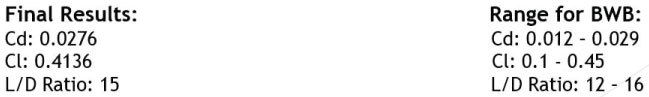
Following figure shows lift and drag coefficient values for our design and normal range for a blended wing body (Figure 8).
Conclusions
As we can see that the results within the range for blended wing UAVs and we got a high value for L/D ratio (15) because of the blended wings. Pressure on the wing section was decreased by using a unique airfoil and varying the aspect ratio on the wing section, as a result we got a low value for coefficient of drag and a higher value for coefficient of Lift.
Future Work
• This study was carried out at a constant speed for cruise condition only. A study comprised of determining the behavior of aircraft for takeoff, climb, descend and landing conditions would be really helpful.
• Based on study at the above described conditions, the design can be than regarded as fit for manufacturing.
References
- Daniel PR (1992) Aircraft design: A conceptual approach. American Institute of Aeronautics and Astronautics, Washington, DC, USA.
- Ira H Abbott (1949) Theory of wing sections. Dover Publications, New York.
- John D Anderson Jr (1991) Fundamentals of Aerodynamics. McGraw-Hill, USA.
- http://bagheri.shahreza.ac.ir/my_doc/bagherishahrezaacir/Bagheri/CFD-gambit%202.2%20tutorial.pdf.
- https://www.scribd.com/document/28582667/Fluent-6-0-User-s-Guide-Vol-1.
- http://www.afs.enea.it/project/neptunius/docs/fluent/html/wbug/main_pre.htm.
- http://www.pmt.usp.br/ACADEMIC/martoran/NotasModelosGrad/ANSYS%20 Fluent%20Theory%20Guide%2015.pdf.
- http://www.nasa.gov/audience/forstudents/5-8/features/whatisaerodynamics- 58.html.
- http://www.grc.nasa.gov/WWW/K-12/airplane/boundlay.html.
Corresponding Author
Tayyab Khan, MS, Department of Mechanical Engineering, Ataturk University Erzurum, Turkey.
Copyright
© 2019 Khan T. This is an open-access article distributed under the terms of the Creative Commons Attribution License, which permits unrestricted use, distribution, and reproduction in any medium, provided the original author and source are credited.