Impact of Crude Oil Emulsion on Pipeline Corrosion
Abstract
The objective of this work is to study the effect of emulsion formation on steel corrosion in a sweet environment in a laboratory scale. Field experience shows that improper sizing of pipelines in the petroleum industry is often caused by a lack of understanding of three-phase flows which are characterized by a gas phase flowing together with a brine-oil liquid phase. The emulsion formation in these systems plays an important role on the corrosion rates of steel pipelines. Therefore, the corrosiveness and stability of the brine-oil mixtures with different water cuts are systematically studied. The necessity to reduce costs in handling fluids requires a high flow rate with an inherent risk for turbulence influencing the stability of the brine-oil mixtures and the corrosion process of steel pipes. These conditions occur especially in offshore environments, in oil and gas productions, in chemical processes and in energy production industries. In previous work, multiphase-flow-loop tests were conducted for thirty hours using a centrifugal pump for promoting a mixture of 20% of light oil crude oil or heavy crude oil + 80% of deionized water, containing 15% of sodium chloride, at 40 ℃ under a CO2 partial pressure of 2.0 bar. In this work, emulsion tests were conducted with heavy, medium, and light crude oil with a water cut of 80% at 40 ℃ for thirty hours, under 1200 rpm stirring, in the presence of CO2. The emulsion stability evaluation was performed by Turbiscan Stability Index (TSI) based on multiple light scattering methods. A comparison between the obtained results in the multiphase-loop and in the Turbiscan Stability Index (TSI) tests showed that the higher emulsion stability contributed to the increase in the corrosion rates.
Keywords
Flow-induced corrosion, Emulsion systems, Pipeline corrosion, CO2 corrosion, Crude oil
Introduction
Emulsions are dispersions with one liquid phase in another and can exhibit stability in the presence of surfactants, macromolecules and solid particles adsorbed at the interface of both. At least two immiscible liquid phases must be present to form an emulsion. Therefore, it is important to know the behavior of a system constituted by a surfactant and two immiscible liquids, generally referred to as oil (O) and water (W) [1-3]. There are three types of emulsions: water-in-oil (W/O) emulsion, oil-in-water (O/W) emulsion and multiple emulsions [2,4].
In emulsion studies, the main attention is focused on interparticle forces or colloid interactions and on the emulsion stability, in terms of demulsification. The work (thermodynamic) for emulsification can be defined as the product between the interfacial tension and the variation of the area generated by the process. This energy must remain stored for some time until the system follows the natural path of minimizing it by decreasing the interfacial area and consequent destruction of the dispersion. Despite their thermodynamic instability, many emulsions are kinetically stable and do not change for long periods. This happens because the barrier potential which prevents aggregation of the particles is high [2].
Oil wells produce single-phase crude oil at first, but it is common for water to occur after some time of production. The water content can be as high as 90% or more before the well becomes uneconomical and is shut down. Under these conditions, the two liquids can form emulsions with high viscosity. The result can be a gel with non-Newtonian properties, and its transportation can be as difficult as very viscous oil. Predicting whether such emulsions are likely to occur and evaluating whether they can cause serious problems typically involve both chemical analysis and flow calculations [5].
In general, there are two important factors that cause emulsion formation in the petroleum industry: turbulent flows and pressure changes in choke valves and other valves during crude oil extraction. As a consequence, the cost of transportation and pumping of crude oil as well as the corrosion risks of the crude-oil processing equipment increase. This is one of the biggest problems in the petroleum industry, especially for mature oil fields for which water quantity accompanying crude oil extraction is high [6].
The presence of CO2 can change the properties of crude oil. The solubility of CO2 in crude oil is often many times greater than in water. The incorporation of CO2 can induce an expansion in the volume of crude oil. The viscosity of crude oil decreases enormously with increasing pressure and temperature. It should also be noted that, in W/O emulsions, a lower viscosity can lead to easier separation of phases a condition that increases the risk of corrosion [7].
In Brazil, about 20% of the oil reserves comprise heavy oil with a viscosity ranging from 20 cP to 400 cP under reservoir conditions. The extraction of heavy oil is more complex and more expensive than that of light oil because the challenges are greater; the refining is more difficult, and the generated derivatives are of lower added value. A significant portion of Brazilian reserves is located in deep or ultra-deep waters. A greater depth of the well tube can result in higher partial pressure of CO2. Therefore, heavy oils associated with high CO2 partial pressure may indicate a higher corrosion risk for pipelines and equipment of deeper wells [8].
In this scenario, the flow assurance in production is a crucial factor considering the high pressures and low temperatures. The main challenges are to reduce production losses by improving operational practices to properly handle highly viscous emulsions, hydrates and paraffin depositions. The characterization of W/O type emulsions is important to improve the confidence in the predictions of the necessary pressures for the flow of emulsions formed mainly by heavy and viscous oils. These problems are aggravated when the fields operate in low temperatures and reach mature ages [9,10].
In Oil and Gas industry, centrifugal pumps are widely employed to lift fluids from wells to topside facilities. Nowadays, it is estimated that approximately 10% of the oil supply in the world is produced with centrifugal pumping installations. In these systems, the high shear and turbulence also can promote the breakup of the phases into small drops, producing dispersions and emulsions which can be O/W or W/O types [11]. Many variables can influence the emulsification process. For instance, the phase viscosity is an important factor since it is related to the efficiency of the stirring process. It is well known that if the difference of the viscosity between the water phase and the oil is high, the emulsification process could be considerably changed. A change in the phase viscosity ratio can produce a change in an emulsion standard inversion line [12]. The increase in emulsion viscosity is due to the large number of small water droplets often leading to increasing the cost of the operation condition [6]. By means of specific emulsification tests, it is possible to better understand the phenomenology of emulsions [12]. This knowledge can be used for corrosion assessment and management of pipelines carrying brine-oil mixtures. In this work, emulsion tests were conducted with heavy, medium, light crude oils plus water cut of 80% at 40 ℃ for thirty hours, with stirring at 1200 rpm, in the presence of CO2. The emulsion stability evaluation was studied through tests performed by Turbiscan Stability Index (TSI) based on multiple light scattering methods. The obtained results were compared with the results of corrosion tests performed in a multiphase-flow loop described in a previous work [1] aiming at contributing to flow-induced corrosion (FIC) understanding.
Methodology
Multiphase-flow tests
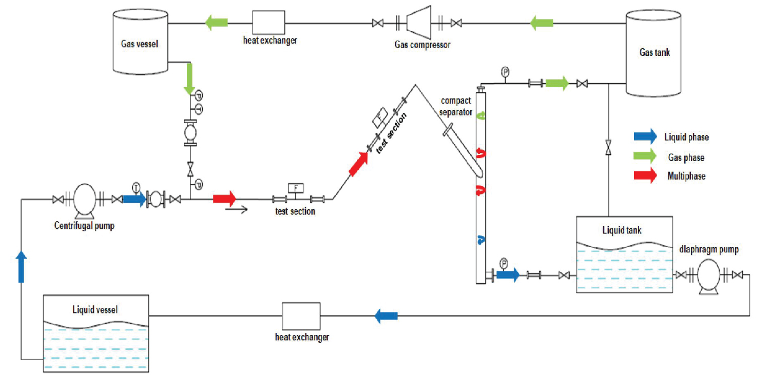
The multiphase flow corrosion loop was built using UNS S31603 austenitic-stainless steel tubes, with a nominal diameter of 38.10 mm for a working pressure of up to 10 bar and temperature of up to 40 ℃. The construction was designed in order to make it possible to carry out simultaneous tests in the horizontal (0°) and in the 45° inclination direction [13]. API 5L X80 steel was used for the preparation of the corrosion-loop test specimens which were made with the diameter dimensions of 15.90 mm by 9.5 mm in height. These specimens were fixing in the test section according to Figure 1 [13] which shows more details of multiphase flow and the pumping processes to which the mixture of water and oil (liquid phase) was subjected for thirty hours of testing.
The liquid phase for the test was composed of light oil (LO - 10 cP) or heavy oil (HO - 150 cP) and a saline solution containing 15% of NaCl. Water cut of 80% (WC 80) of the NaCl solution and 20% of LO or HO under a CO2 partial pressure of 2.0 bar was used. The procedure of the O2 removal from the liquid and gaseous phases is necessary to guarantee an environment with no oxygen (< 10 ppb) and to promote the tests under the action of CO2 gas.
Emulsification tests
Tests were conducted with the light oil and the heavy oil used in the multiphase-flow test plus a medium crude oil, all of them with a water cut of 80% at 40 ℃ for thirty hours, under stirring, with a CO2 pressure of 2.0 bar. For stirring the mixture, an impeller with a rotation of 1200 rpm was used. The adopted stirring represents the mean values of the rotation of the electric motor of the centrifugal pump used in the multiphase-flow corrosion loop [14,15].
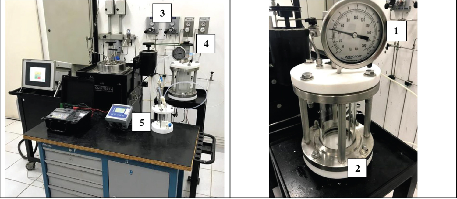
Figure 2 shows the emulsion test cell (2) which holds up to 3 bar pressures. As can be seen, the cell is provided by gas inlets and outlets (3) to perform conditions similar to those observed in the loop with constant test gas pressure. The system pressure was checked by a manometer (1) and a rotor with magnetic coupling (4) was coupled in order to transmit 1200 rpm to the impeller mounted inside the pressure vessel which was manufactured from a borosilicate tube with Teflon flanges at both ends (2). For guaranteeing the efficiency of O2 removal, an optical sensor (5) model Mettler Toledo In Pro6970i was used. A maximum limit of the oxygen of 10 ppb was adopted. A thermostat with an internal bath was used to maintain the test temperature at 40 ℃ for thirty hours.
Emulsion microstructure characterization
The microstructures of obtained emulsions both in the loop test and in the emulsion test cell shown in Figure 1 and Figure 2 were obtained through a stereomicroscope examination (Leica Fusion Optics M205C).
Analysis of emulsion instability by optical turbidimetry
As emulsions are thermodynamically unstable systems, the dispersed phase can coalesce and flocculate. The formed floccules can sediment or float at the surface. All these processes directly influence the turbidity and the opacity of the emulsion. In this case, it is important to define which destabilization mechanisms are taking place. Thus, immediately after the emulsification cell test is done, the optical turbidimetry studies were performed based on a multiple light scattering method by a TURBISCAN Lab Expert analyzer to monitor the optical properties which allow a more reliable and accurate analysis. The Turbiscan takes readings at various pre-programmed time intervals and superimposes the curves on a graph to show the emulsion's destabilization. In this work, the scans were scheduled to be done for one day for each hour continuously at 40 ℃. The final result of this analysis is presented by two different graphs, one by a transmitted light (T) profile and the other by a backscattered light (BS) profile. A sample was previously collected from the emulsion cell and placed in a quartz glass cell. The measurements were done by scanning vertically the sample bottle up to the height of 50 mm, for 24 hours.
Results and Discussion
Multiphase loop test
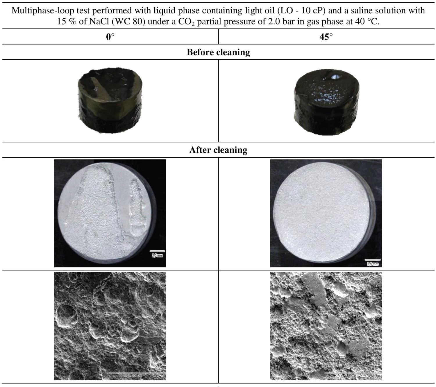
After loop tests are completed for light and heavy oils, the specimens in the test section both in the horizontal (0°) and inclined position (45°) were disassembled and subjected to visual inspection and examination by Scanning Electron Microscope (SEM) and Optical Microscopy (OM).
Figure 3 shows the appearance and the SEM images of the specimens the tested with light oil. The corrosion rates of these specimens reached values in the order of 67 mm/y. After the cleaning with as a suitable soap, no visible layer of iron carbonate was observed which indicate that the expected iron carbonate formed due to the presence of CO2 were removed by the hydrodynamic effect.
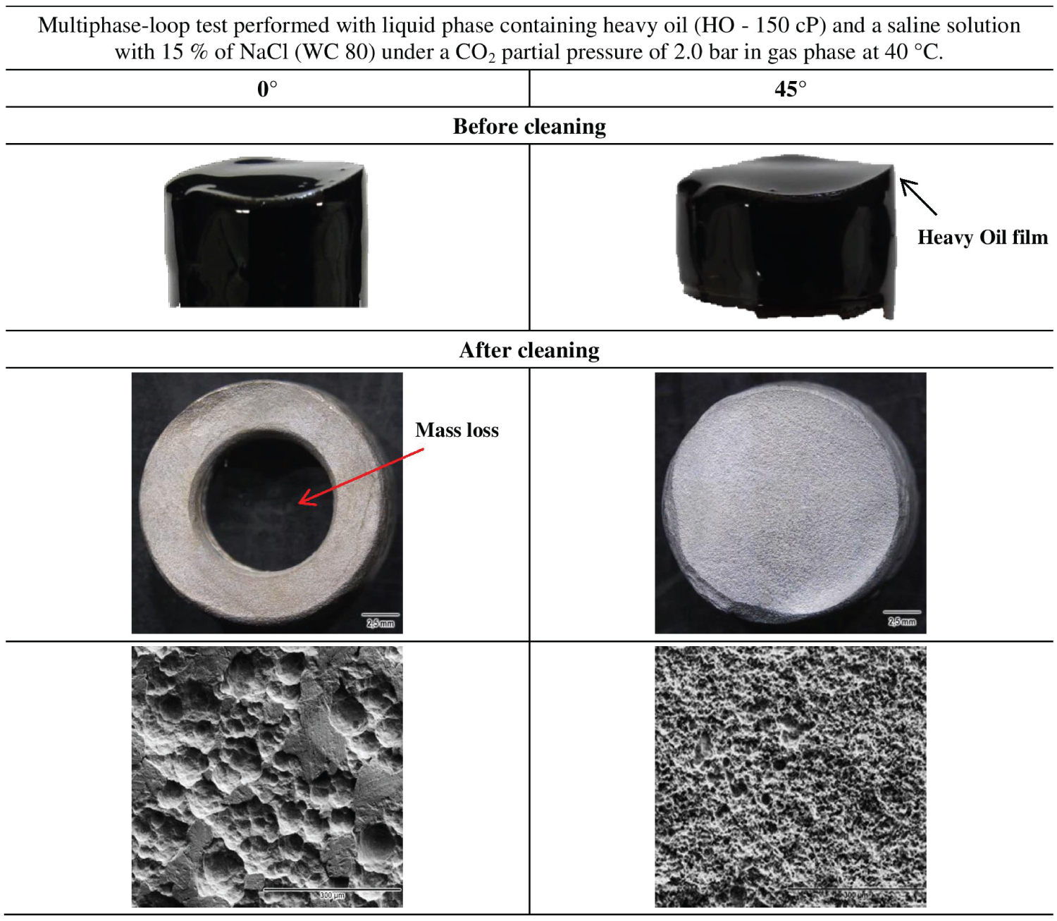
For heavy oil tests, the corrosion test specimens, both installed at a horizontal position and at a 45° position were covered with a thick oil film with appearance and viscosity quite different from the original HO (Figure 4). The corrosion rates of these specimens were the highest values among the tests performed in the loop under different conditions (values of more than 170 mm/y were obtained). After the cleaning with a suitable soap, no visible layer of iron carbonate was observed which means that the specimens were under an erosion-corrosion process, i.e., the formed iron carbonate layer was removed under the adopted flow regime. For the 0° condition, the surface of the specimen showed a significant mass loss up to the point of removing its flat original surface due to the highly aggressive corrosion-erosion process.
The SEM and OM images Figure 4 after cleaning the specimens tested in heavy oil illustrate the strong hydrodynamic effect associated with corrosion. This behavior may be related to the fluid characteristics and the distribution of stresses on the surfaces of the specimens in the horizontal and inclined positions.
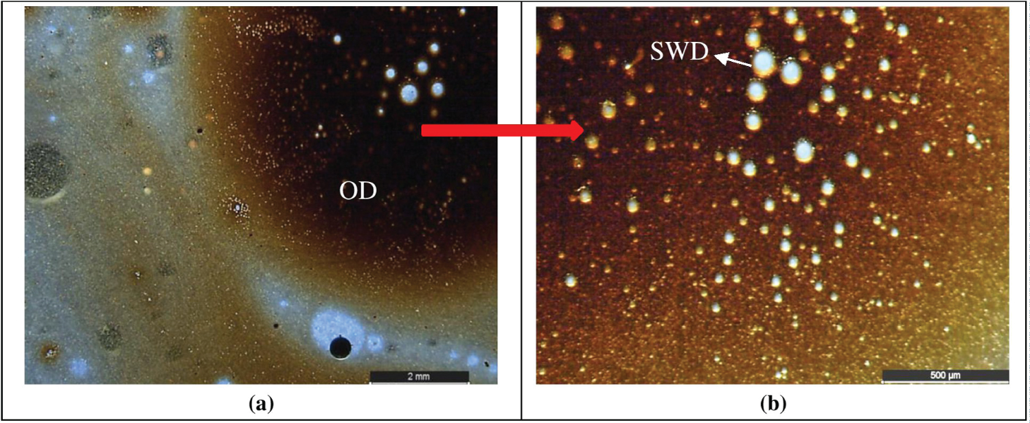
After the loop test performed with the heavy oil, a significative increase of the viscosity of the liquid phase was verified. For this reason, a sample of the liquid phase was taken. The same procedure was not done with the liquid phase of the light-oil test. The visual inspection of this sample (heavy oil and water) showed three different phases: water at the bottom; emulsion at the middle (transition phase) and oil phase at the top. A small sample of the transition phase was taken from the liquid-phase sample. Figure 5 shows the transition phase microstructures obtained through a stereomicroscope. Figure 5A shows that there are oil droplets in the water (O/W emulsion). A greater magnification view of one of the oil droplets is shown in Figure 5B. The presence of small water droplets (SWD) within the observed oil droplet (OD) can be perceived a W/O emulsion.
For many crude oils, the presence of a water cut greater than 35% will result in a continuous water phase for a fully mixed oil/water system such that corrosion then becomes a potential risk [16,17].
Therefore, it was decided to better understand this phenomenon to find out possible causes of such high corrosion rates.
Emulsification Tests
Immediately after the emulsification test, samples of each type of oil were collected. One part is kept at rest to observe the separation process and the other part is sent to the beginning of the analysis on the Turbiscan.
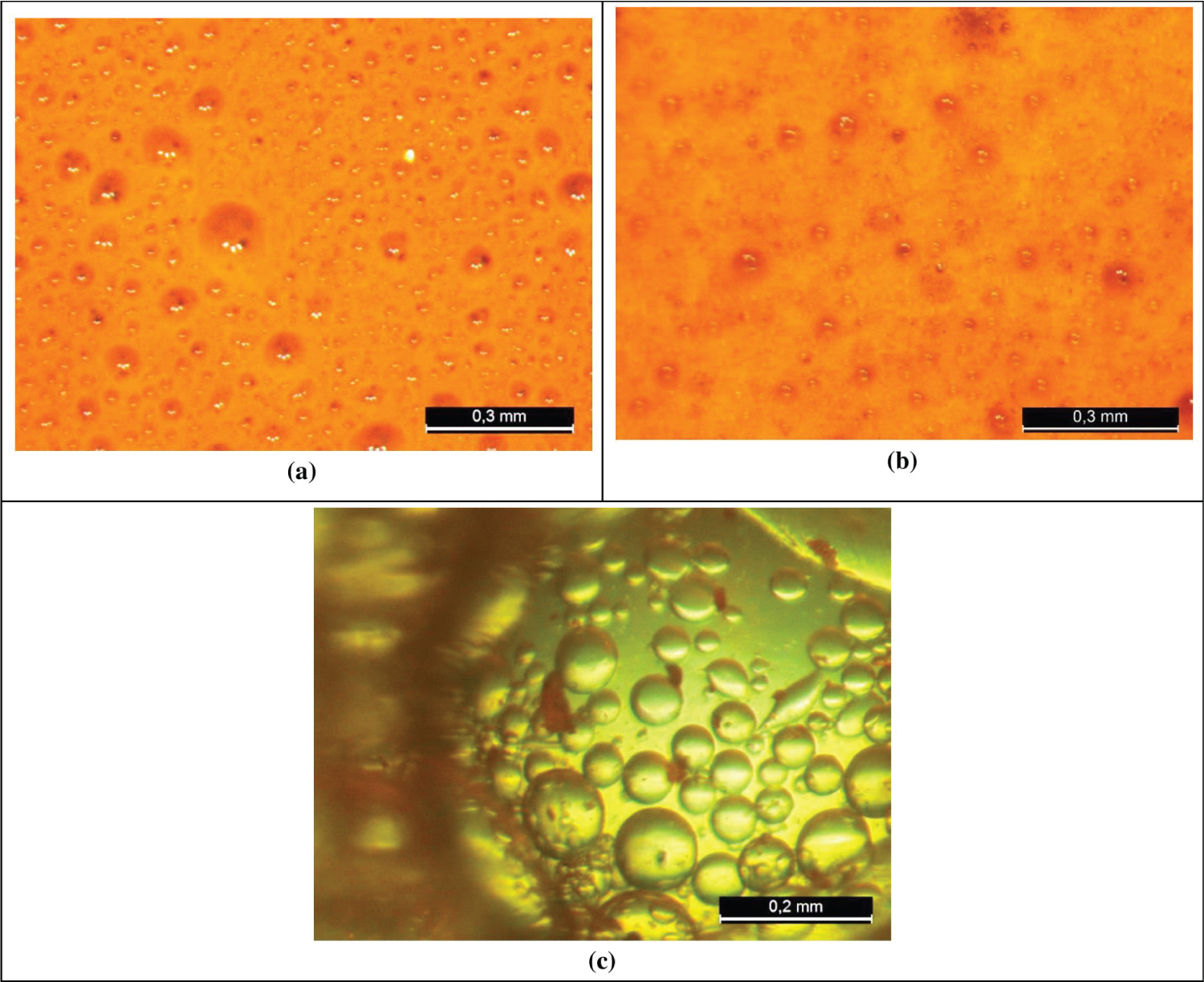
Figure 6 shows the images obtained through a stereomicroscope examination of the (a) heavy oil, (b) medium oil and (c) light oil after 30 h stirring, at 40 ℃, in the emulsion-test cell.
From Figure 6A, heavy oil, we can verify the presence of water droplets in the oil phase indicating a W/O emulsion which is also known as “chocolate mousse” or “mousse” among oil spill workers [3]. In Figure 6B, medium oil, we can observe a similar behavior with water droplets in the oil phase indicating a W/O emulsion. Studies show that a W/O emulsion presents the highest value of viscosity at the critical water cut (60% to 80%), i.e., at the inversion point [4]. For light oil, you can see drops of water inside the oil but in a different distribution mode as shown in Figure 6C.
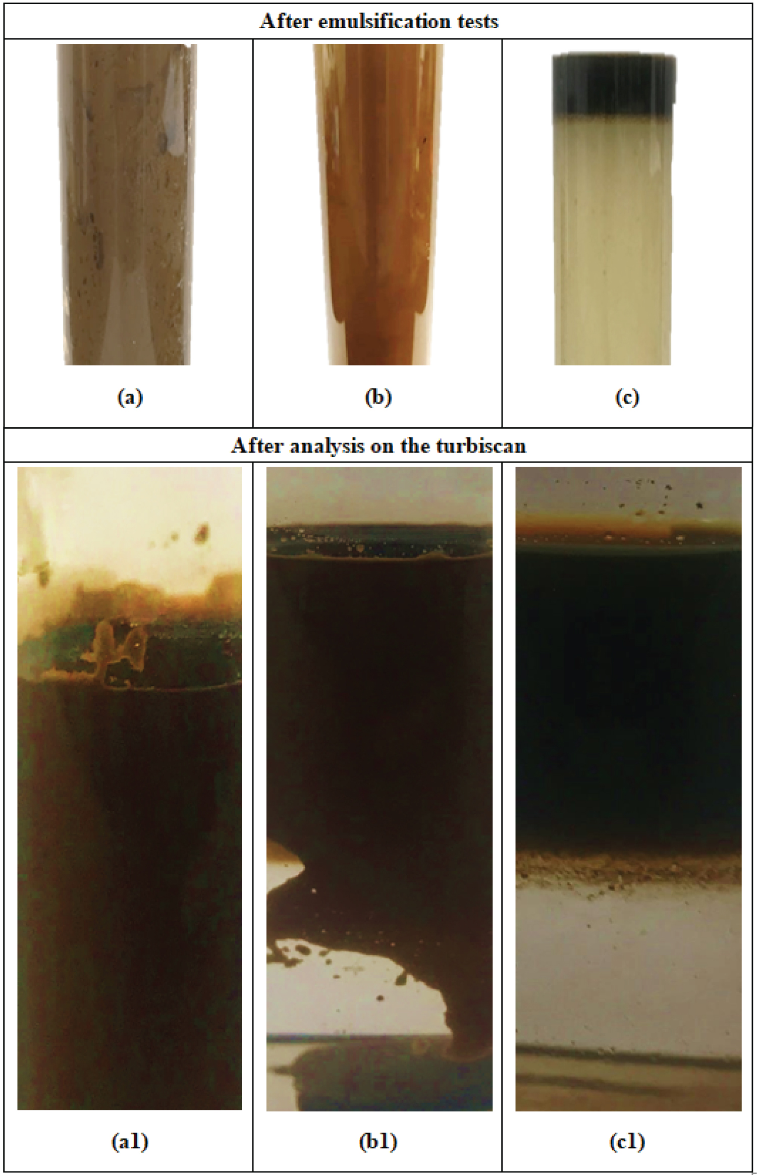
Figure 7 shows the images of the visual aspect of the oils after the emulsification tests and after the analysis on the Turbiscan, respectively: (a) and (a1) for the heavy crude oil; (b) and (b1) for the medium crude oil and (c) and (c1) for the light crude oil.
The most important detail of the visual observation is that the heavy and medium oils were much more viscous and stable, with an aerated aspect and with retention of almost all water volume (Figure 7A and Figure 7B). The higher viscosity was perceived during the manipulation of the sample.
The light oil presented a different behavior with a quick separation soon after the sample collection, leaving the water a little whitish and the oil lighter, but without major visible changes in viscosity and aeration (Figure 7C).
From Figure 7A1, it is possible to observe that the heavy oil presents greater stability in the formed W/O emulsion. When compared the heavy oil with the medium (Figure 7B1) and the light oil, (Figure 7C1) clearly light oil is more unstable. For light oil, soon after the emulsification test, the rapid separation of the O/W emulsion can already be observed. In the literature the corrosiveness of the W/O emulsion strongly depends on its stability and a method is suggested to avoid pipeline corrosion by keeping the emulsion stable [18]. Additionally, researchers have observed in multiphase-slug-flow experimental studies that an increase in the viscosity and the flow rate (higher shear stress) promote the removal of corrosion products and thus the increase in corrosion damage [4].
Analysis of emulsion instability by optical turbidimetry
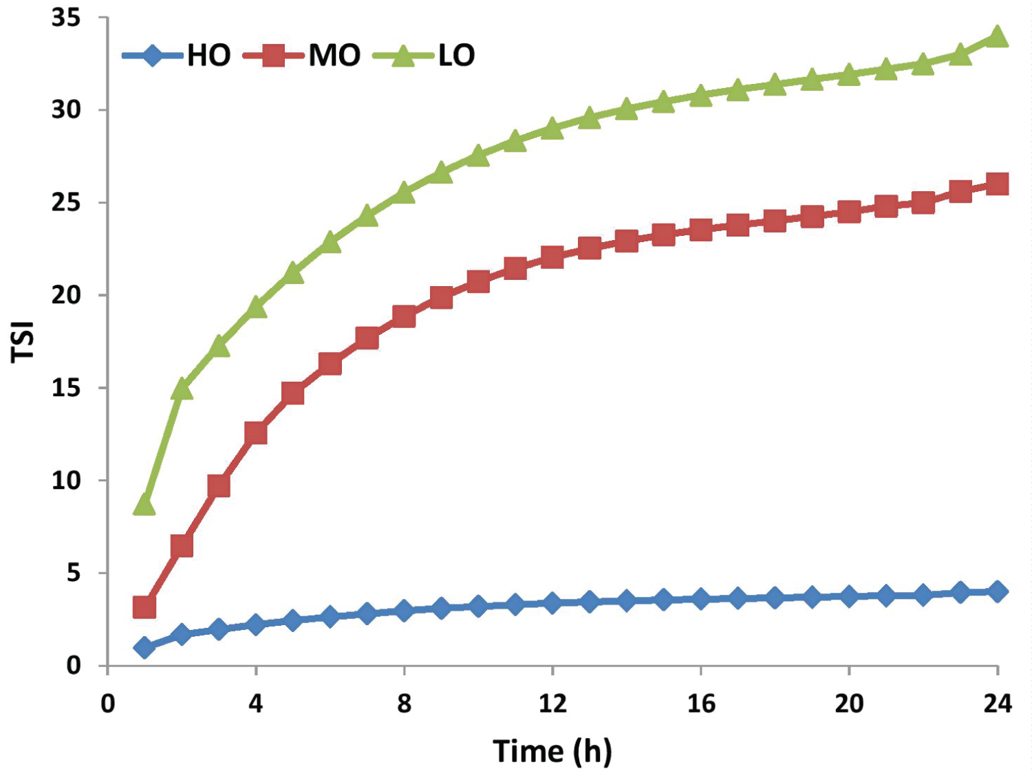
The emulsion stability was characterized using the Turbiscan to evaluate the kinetic of Stability Index (TSI). The TSI value is calculated based on Equation 1 [19].
Where scani (h) is the light intensity of the i-th scan at a height of h, and H is the total height of the measured sample. The combined effect of multiple instability phenomena on light intensity changes can be characterized by TSI. The larger the TSI value, the more unstable the system. Figure 8 presents the TSI of the three crude-oil emulsions for 24 hours. As can be seen from TSI, the emulsions stability results are as follows:
HO > MO > LO
It is important to mention that the measurement in the Turbiscan considers not only creaming but also the flocculation and the coalescence phenomenon.
Conclusions
The results of emulsion cell test in the laboratory with light oil, medium oil and heavy oil + water cut 80%, under 2.0 bar of CO2 pressure and 40 ℃ allowed us to conclude that the behavior of the emulsion system (stability of emulsion) is strongly correlated with the type of crude oil type. Heavy oil formed the most stable emulsion followed by the medium and light oil.
The corrosion rate obtained with the heavy oil in the multiphase-loop test was higher than that obtained with light oil. In both tests an iron carbonate layer was not detected on the surface of the tested specimens showing that the erosion corrosion process is the main corrosion mechanism. This difference can be ascribed to the higher stability of HO/W emulsion.
References
- Silva CA, Filho DRN, Nunes GMB, et al. (2019) Corrosion in multiphase slug flow loop in deep-water oil and gas exploitation, in OTC-29720-MS: 1-28.
- Sjöblom J (2006) Emulsions and emulsion stability. (2nd edn), USA.
- Wong SF, Lim JS, Dol SS (2015) Crude oil emulsion: A review on formation, classification and stability of water-in-oil emulsions. J. Pet Sci Eng 135: 498-504.
- Wang ZM, Zhang J (2016) Corrosion of multiphase flow pipelines: The impact of crude oil. Corro Rev 34: 17-40.
- Bratland O (2010) Pipe Flow 2, Multiphase flow assurance.
- Abdulredha MM, Aslina HS, Luqman CA (2020) Overview on petroleum emulsions, formation, influence and demulsification treatment techniques. Arab J Chem 13: 3403-3428.
- Wang ZM, Song GL, Zhang J (2019) Corrosion control in CO2 enhanced oil recovery from a perspective of multiphase fluids. Front. Mater 6: 1-16.
- Santos R, LohA W, Bannwart C (2014) An overview of heavy oil properties and its recovery and transportation methods. Braz. J Chem Eng 31: 571-590.
- Estrella G, Rondón-González M, Sadtler V, et al. (2003) The importance of Brazilian deepwater activities to the oil industry technological development. Proc Annu Offshore Technol 47: 1-7.
- Rondón-González M, Sadtler V, Marchal P, et al. (2008) Emulsion catastrophic inversion from abnormal to normal morphology. 7. Emulsion evolution produced by continuous stirring to generate a very high internal phase ratio emulsion. Ind Eng Chem Res 47: 2314-2319.
- Perissinotto RM, Monte Verde W, Perles CE, et al. (2020) Experimental analysis on the behavior of water drops dispersed in oil within a centrifugal pump impeller. Exp Therm Fluid Sci 112: 109969.
- Kalra A, Venkatraman A, Raney KH, et al. (2012) Prediction and experimental measurements of water-in-oil emulsion viscosities during alkaline/surfactant injections. Oil Gas Facil 3: 34-43.
- Silva CA, Filho DR, Nunes GM, et al. (2019) The design and development of a small-scale, multiphase flow loop for the study of corrosion in sour/sweet gas environments. Rio Pipeline Conf Exhib 1-10.
- Ge JJ, Zhang GC, Jiang P, et al. (2012) Study on influencing factors of chemical flooding for heavy oil. J Dispers Sci Technol 33: 278-286.
- Colmanetti ARA, de Castro MS, Barbosa MC, et al. (2018) Phase inversion phenomena in vertical three-phase flow: Experimental study on the influence of fluids viscosity, duct geometry and gas flow rate. Chem Eng Sci 189: 245-259.
- Kermani MB, Harrop D (1996) The impact of corrosion on oil and gas industry. SPE Prod. Facil 186-190.
- Xu XX (2007) Study on oil-water two-phase flow in horizontal pipelines. J Pet Sci Eng 59: 43-58.
- Wang ZM, Liu XT, Han X, et al. (2015) Managing internal corrosion of mild steel pipelines in CO2-enhanced oil recovery multiphase flow conditions. Energy Technol 3: 225-233.
- Wang K, Li G, Zhang B (2018) Opposite results of emulsion stability evaluated by the TSI and the phase separation proportion. Colloids Surfaces A Physicochem Eng Asp 558: 402-409.
Corresponding Author
CA Silva, Technological Research Institute, 05508-901, Sao Paulo, Brazil.
Copyright
© 2021 CA Silva, et al. This is an open-access article distributed under the terms of the Creative Commons Attribution License, which permits unrestricted use, distribution, and reproduction in any medium, provided the original author and source are credited.

