Polyethylene Finite Element Wear Simulation Evaluated by Clinical RSA Wear Measurements
Abstract
Introduction
Documentation on medical devices should be mandatory before clinical use, and phased introduction is warranted to avoid unfortunate failures at larger scale. Biomechanical computer simulation could be a valuable pre-clinical tool for evaluation of new commercial orthopaedic implants, and this study examined the feasibility of computer simulations of polyethylene wear in hip prosthesis.
Methods
A Finite Element (FE) model of a metal-on-polyethylene bearing from a total hip arthroplasty (was generated and several mechanical parameters representing simulated Polyethylene (PE) wear were extracted. The simulation results were compared to clinical in vivo model-based Radiostereometric (RSA) measurements of PE wear in 14 young patients with mean follow-up of six years.
Results
The clinical RSA measured PE wear was primarily directioned in the posterior-superior part of the liner, and simulated mechanical parameters of stresses and strains compared to the clinical wear measurements. All parameters for the simulation model were located in the posterior-superior part of the liner within one standard deviation of the clinically RSA measured PE wear, but normal strain indicated of an interrelation to the RSA measured PE wear.
Conclusion
FE biomechanical computer analysis was feasible for PE wear simulation using selected mechanical parameters for wear prediction.
Keywords
Wear simulation, Finite element analysis, Radiostereometric analysis, Mechanical parameters, Polyethylene wear
Introduction
Hip implant surgery is a commercial and clinical success, and numerous hip arthroplasties have been inserted in patients worldwide. Even the earliest cemented hip implants have proven durable, but optimizations and new implant technology is regularly introduced by the industry. Ideally, new orthopaedic implant technology would require protocolled use and at least some years of follow up in scientific studies before a general commercial marketing was allowed, and a phased or step-wise introduction including pre-clinical testing has been suggested [1,2]. One of the most common causes of failure of hip arthroplasty is Polyethylene (PE) wear due to, particle induced periprosthetic osteolysis and subsequent aseptic loosening and prosthetic revision surgery [3]. Especially in younger patients and with use of bigger femoral heads PE wear-related implant failure is a problem, and in recent years production of more durable (crosslinking) and less oxidation sensitive (vitamin E doped) PE liners have been introduced. Currently, the most precise clinical method (the gold standard) to measure PE wear is Radiostereometric Analysis (RSA), which measures femoral head penetration into the acetabular cup in 3 dimensions [4-6]. However, clinical wear of newer PE liners is difficult to measure before at least a mid-term follow-up [7], and therefore, a good pre-clinical method for wear-prediction of new PE products is warranted in order to stop eventual bad-performing PE products early during a step-wise introduction. Finite Element (FE) analysis, a computer simulation model, has formerly been used to predict polyethylene wear, and mechanical parameters [8,9] based on functions of roughness [10], sliding velocity [11], or slide distance [8,9] have shown correlation with PE wear as proportional contributors to volumetric wear. However, contact pressure and cross-shear motion seem to correlate best with wear [10,12,13]. Hence, computational studies using FE analysis seem useful in evaluating the effect of these mechanical parameters in new PE materials. However, the validity of computational methods needs to be confirmed by comparison to in vivo data [14,15]. Earlier studies have compared FE wear simulations to experimental in vitro simulations from multi-directional pin-on-plate testers [16] and in hip simulators [9], but found discrepancy between measured and predicted PE wear ranging from 4.1% [8] to a factor 2-3 [16]. Although in vitro testing provide important control over the testing situation, such as an accurate FE setup [17], concern has been raised that the predictions of PE wear based on FE analysis results are only valid for the applied and often single set of loading conditions. In vivo validation of FE estimated wear is more clinically relevant and include the numerous facets of wear i.e. creep, bedding-in, running-in, backside wear and true wear [18]. In our study we wanted to compare computed FE results of PE wear with in vivo RSA measured clinical PE wear data at a six years of follow-up.
Material and Methods
Patients
14 young patients (7 women) at mean age 53 years (range 44-65) and mean body weight of 84 kg (range 61-114) were seen for midterm follow-up (mean 6.1 years; range 5.3-7.1). The acetabular components were hydroxyapatite-coated metal shells (Mallory-Head, Biomet Inc, Warsaw, IN) mean size 55 (range 50-52). Only Ultra-High-Molecular-Weight-Polyethylene (UHMWPE) gamma sterilized ArCom liners mean size 23.4 (range 23-25) articulating with 28 mm CoCr femoral heads were used. Femoral stems were cementless hydroxyapatite-coated Bi-Metric stems (Biomet Inc, Warsaw, IN).
The Radiostereometric Analysis (RSA)
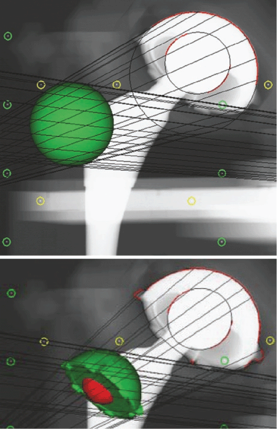
The stereo-radiographs were obtained simultaneously with the tubes positioned in 20 degree converging angles over the patient and in relation to a uni-planar calibration box (Box 24, Medis Specials, Leiden). Supine postoperative and approximately 6 years double examination follow-up stereoradiographs were obtained. This allowed reconstruction of a 3D coordinate system and for the calculation of relative model displacement (femoral head penetration into the acetabular cup) in sequential radiostereographs. An Elementary Geometrical Shape (EGS) sphere model was used for the head and a CAD (Computer Aided Design) model was used for the acetabular cup [19]. Two analyses were performed per patient for an averaged measure of the double examinations. Precision of the method has been presented in an earlier study [7]. The output was three translations (mm) along the orthogonal axes (x = medial-lateral, y = inferior-superior, z = anterior-posterior). 2D (two dimensional) and 3D (three dimensional) wear vectors were calculated using Pythagoras theorem as 2D wear vector = the square root of x2 + y2 (equ1) and 3D wear vector = square root of x2 + y2+ z2 (equ2). Measurements of cup inclination and anteversion were read from the MB RSA software (RSAcore, Leiden, The Netherlands) using the positions of the fitted cup models (Figure 1).
The FE analysis
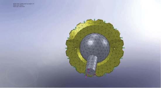
FE analysis was performed using the finite element code Solidworks™. The FE model was a 3D model of an ArCom PE liner (Biomet, Europe) made from UHMWPE and with a Ringloc locking-mechanism for fixation in the acetabular metal shell. The geometric 3D model for this was provided by courtesy of Biomet™, and a FE mesh of the liner was generated with a total of 10,960 4-node volumetric tetrahedral elements. The material property for the ArCom (UHMWPE) liner was provided by courtesy of Biomet™. The PE liner was positioned in the ideal position of 15 degrees anteversion and 45 degrees inclination. The acetabular cup was simulated with ideal contact between the metal cup and PE liner. Total osseointegration/fixation of the metal cup was simulated by completely locking the backside of the PE liner in all directions. The load of gravity of an 80 kg person was applied to the FE model in a standing position through a CoCr femoral prosthetic head and neck. The head and liner contacted each other with contact elements. The FE mesh of the liner and femoral head is shown in Figure 2.
Verification of the wear analysis
The FE results were compared to two parameters of RSA wear data; estimated resultant wear vectors (2D and 3D wear) and wear in three translational vectors of the orthogonal coordinate system. The three translational vectors of the RSA data with one SD (Standard Deviation) were superimposed into the FE model by projecting them onto the surface of the liner. This 'volume' was regarded as the point in the liner with maximal wear. Then the computed FE data from the inner liner surface were analysed and compared to the locations of maximal contact pressure, stress intensity, Von Mises stress, strain energy density and total strain. The distances from maximal "RSA wear" to the maximum of the calculated parameters were measured. The three directional and normal stresses and strains, the three principal stresses and strains and lastly the three sheer stresses and strains for the inner surface of the liner were compared to the three translational vectors from the RSA wear measurements, and a similar procedure was also performed for the points of maximal contact pressure, stress intensity, Von Mises stress, strain energy density and total strain. Additionally, translational/directional FE data were also retrieved from the whole inner liner surface for comparison with RSA data. These were compared as a ratio to the total sum of the structural parameters to a ratio of the similar translational RSA vector to the resultant RSA "3D wear", since these parameters were not directly comparable:
Where "∂" was the FE generated structural parameter for the inner surface of the liner - derived either as a parameter summarized from the whole inner surface of the liner or the point of maximum for the given structural parameter. "l" was the translational vector from the RSA experiment. "n" was one of the three directions in the orthogonal coordinate system. "total" symbolized summarized FE and RSA results for the inner surface of the liner and resultant wear, respectively.
Results
The RSA data
Vector PE wear was -0.09 (SD 0.27) mm, 0.53 (SD 0.30) mm, and -0.19 (SD 0.52) mm in the X-direction, Y-direction and Z-direction, respectively. Femoral head penetration total mean for equ1. and equ2. were 0.61 (SD 0.27) mm and 0.77 (SD 0.38) mm, respectively. The Cup was positioned with a mean of 47.6 degree (SD 9.1) in inclination and a mean of 16.0 degree (SD 5.4) in anteversion.
The FE simulation and wear comparison
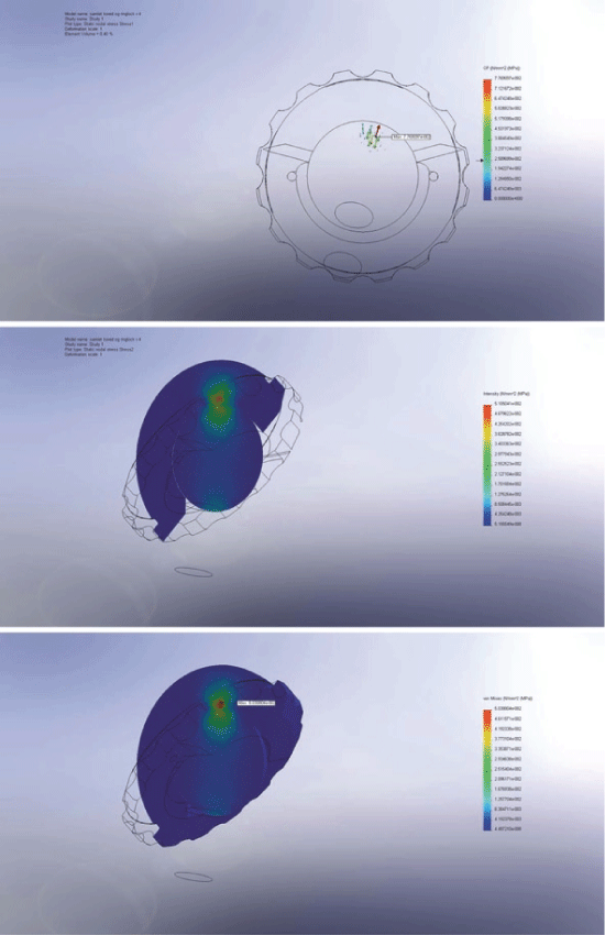
The difference between the location of maximal wear measured by RSA and maximal contact pressure, stress intensity, Von Mises stress, strain energy density and total strain on the inner liner surface were all well within the range of 1 SD of the RSA data. The strain parameters of total strain and strain energy density were closest to the location of maximal RSA wear, hence best indicated of an interrelation. Figure 3 shows the FE simulation.
The ratio differences between the translational/directional structural parameters and the translational RSA wear vector were calculated. Table 1 illustrates the differences in ratios between maximal and inner liner structural parameters and the translational RSA wear. For the maximal translational/directional parameters shear stress and principal strain indicated of an interrelation to the translational RSA wear vectors and for the total inner liner surface normal strain and principal stress indicated of an interrelation.
Discussion
The key findings were that simulated mechanical parameters for the given load were within 1 SD of the location of the maximal RSA evaluated PE wear, where strain parameters of total strain and strain energy density were closest to the maximal wear measured by RSA. Moreover, the mechanical parameters maximal shear stress and principal strain and overall normal strain and principal stress seemed to correlate best to the translational RSA wear vectors. Overall, normal strain gave the best estimate of wear in the FE wear analysis, but if a stress parameter should be used, shear stress would give the best estimate. It should be added that our methods of 'wear simulation' only is an indication of an interrelationship in between FE analysis results and wear, and further verification might be to perform analyses of several different polyethylene liners to verify the method.
This study was a 'sensitivity' study with comparison between FE simulated mechanical parameters and in vivo RSA data, which is the first of it kind to our knowledge. Previously we have examined the 3D resultant, total wear vector to similar one directional FE analysis results as for example strain energy density, but in this study we have elaborated the previous study by adding analysis of each vectorial RSA predicted wear results to their vectorial FE simulation results [20-23]. However, this should be regarded as a pilot study, where further methodological improvements in simulation should be added to improve the inherent limitations for future studies; our assumption of a simple load in stance needs a more detailed load to simulate the wear and tear of daily living. The femoral stem and cup were simulated with approximated assumptions in the boundary conditions, effect of contact stresses to PE wear was not included in the simulation model and a more elaborate FE model with a wider focus could be setup to simulate i.e. bone in-growth and interface conditions. Moreover, the biological processes of living tissue and interaction between tissue and implant including effects of lubrication were omitted in this simulation. Further, the time dependent effect of head damage and oxidative degradation of the PE, and also head size which is known to increase wear clinically, was left out, because realistic simulation solutions of these parameters are not available. Overall, the computational predictions assumed that for example surface Von Mises stress was linear proportional to volumetric wear. This would be true for metal-on-metal surfaces, but for a metal head on a PE surface-bearing one would also have to consider the effects of plastic deformation (creep) and strain softening. Properly a purely linear relationship between aforementioned parameters would no longer be applicable. Despite the aforementioned limitations the FE wear predictions were confirmed when evaluated against the prospective in vivo RSA results, and we consider the wear predictions are valid within the limitations of the chosen methods of simulation as mentioned above.
For the RSA data the large ranges for the translational wear raise concern in regards of accuracy, especially for the Z-axis which was out of plane for the cup. For these reasons we did not perform an FE based estimate of yearly wear rate, since more RSA data would be needed in order to extrapolate to a normal population. Especially, since the data were collected from a young patient group. However, for future studies it would be attractive to predict the approximate time for femoral head penetration to predict when complete liner wear through will likely occur. This estimate would be based on a yearly steady state wear rate derived from FE wear analysis. It would especially be attractive if patient specific factors such as cup and stem position could be included in such a study since, potentially, a safe individualized time plan for long term total hip arthroplasty control examinations could then be calculated.
Conclusion
The FE derived strain parameters seem to be the best measure for prediction of long-term steady-state wear for UHMWPE, when validating FE based wear predictions against in vivo RSA data.
Conflict of Interest Statement
None declared.
References
- Malchau H (2000) Introducing new technology: a stepwise algorithm. Spine (Phila Pa 1976) 25: 285.
- Nelissen RG, Pijls BG, Kärrholm J, et al. (2011) RSA and regestries: the quest for phased introduction of new implants. J Bone Joint Surg Am 93: 62-65.
- Jacobs CA, Christensen CP, Greenwald AS, et al. (2007) Clinical Performance of highly cross-linked polyethylenes in total hip arthroplasty. J Bone Joint Surg Am 89: 2779-2786.
- Valstar ER, Vrooman HA, Toksvig-Larsen S, et al. (2000) Digital automated RSA compared to manually operated RSA. J Biomech 33: 1593-1599.
- Borlin N, Thien T, Karrholm J (2002) The precision of radiostereometric measurements. Manual vs. digital measurements. J Biomech 35: 69-79.
- Valstar ER, de Jong FW, Vrooman HA, et al. (2001) Model-based Roentgen stereophotogrammetry of orthopaedic implants. J Biomech 34: 715-722.
- Stilling M, Larsen K, Andersen NT, et al. (2010) The final follow-up plain radiograph is sufficient for clinical evaluation of polyethylene wear in total hip arthroplasty. A study of validity and reliability. Acta Orthop 81: 570-578.
- Maxian TA, Brown TD, Pedersen DR, et al. (1997) Finite element analysis of acetabular wear. Validation and backing and fixation effects. Clin Orthop Relat Res 334: 111-117.
- Maxian TA, Brown TD, Pedersen DR, et al. (1996) The Frank Stinchfield Award. 3-Dimensional sliding/contact computational simulation of total hip wear. Clin Orthop Relat Res 333: 41-50.
- Brown TD, Stewart KJ, Nieman JC, et al. (2002) Local head roughening as a factor contributing to variability of total hip wear: a finite element analysis. J Biomech Eng 124: 691-698.
- Pedersen DR, Brown TD, Maxian TA, et al. (1998) Temporal and spatial distributions of directional counterface motion at the acetabular bearing surface in total hip arthroplasty. Iowa Orthop J 18: 43-53.
- Bragdon CR, O'Connor DO, Lowenstein JD, et al. (1996) The importance of multidirectional motion on the wear of polyethylene. Proc Inst Mech Eng H 210: 157-165.
- Kang L, Galvin AL, Brown TD, et al. (2008) Quantification of the effect of cross-shear on the wear of conventional and highly cross-linked UHMWPE. J Biomech 41: 340-346.
- Christian Wong, P Martin Gehrchen, Thomas Kiaer (2010) Can Additional Experimental Data in Humans Verify the Finite Element-Based Bone Remodelling Algorithm? The Open Spine Journal 2: 12-16.
- Wong C, Gehrchen PM, Kiaer T (2008) Can experimental data in humans verify the finite element-based bone remodelling algorithm? Spine (Phila Pa 1976) 33: 2875-2880.
- Kang L, Galvin AL, Fisher J, et al. (2009) Enhanced computational prediction of polyethylene wear in hip joints by incorporating cross-shear and contact pressure in addition to load and sliding distance: effect of head diameter. J Biomech 42: 912-918.
- Barbour PS, Barton DC, Fisher J (1997) The Influence of stress conditions on the wear of UHMWPE for total joint replacements. J Mater Sci Mater Med 8: 603-611.
- Sychterz CJ, Engh CA Jr, Yang A, et al. (1999) Analysis of temporal wear patterns of porous-coated acetabular components: distinguishing between true wear and so-called bedding-in. J Bone Joint Surg Am 81: 821-830.
- Kaptein BL, Valstar ER, Spoor CW, et al. (2006) Model-based RSA of a femoral hip stem using surface and geometrical shape models. Clin Orthop Relat Res 448: 92-97.
- Wong C, Stilling M (2010) Tribology in Total Hip Arthroplasty. Polyethylene Wear in Total Hip Arthroplasty for Suboptimal Acetabular Cup Positions and for Different Polyethylene Types: Experimental Evaluation of Wear Simulation by Finite Element Analysis Using Clinical Radiostereometric Measurements, 135-158.
- Lin YT, Wu JS, Chen JH (2016) The study of wear behaviors on abducted hip joint prostheses by an alternate finite element approach. Comput Methods Programs Biomed 131: 143-155.
- Watanabe K, Kyomoto M, Saiga K, et al. (2015) Effects of Surface Modification and Bulk Geometry on the Biotribological Behavior of Cross-Linked Polyethylene: Wear Testing and Finite Element Analysis. Biomed Res Int 2015: 435432.
- Gao Y, Chai W, Wang L, et al. (2016) Effect of friction and clearance on kinematics and contact mechanics of dual mobility hip implant. Proc Inst Mech Eng H 230: 39-49.
Corresponding Author
Christian Wong, Department of Orthopaedics, Hvidovre Hospital, Kettegård Alle 30, 2650 Hvidovre, Denmark.
Copyright
© 2017 Wong C, et al. This is an open-access article distributed under the terms of the Creative Commons Attribution License, which permits unrestricted use, distribution, and reproduction in any medium, provided the original author and source are credited.


