Plasma 3D-Priting of Micro-Punch Array for Fine Embossing into Biomedical Titanium Works
Abstract
Biomedical titanium parts and tools required for tailored fine micro-textures to have their surface anti-bacteria. Formation of micro-grooves into a titanium plate by micro-embossing was the first step toward mass-production of titanium parts and tools with anti-bacteria surfaces. Plasma 3D-printing was proposed to fabricate a micro-punch array to transcribe the micro-groove textures into titanium plate. This material processing consisted of three steps; 1) Micro-patterning of two dimensional micro-groove model onto the AISI316 die substrate, 2) Plasma nitriding to transform this micro-pattern to the hardness profile and 3) Mechanical removal of low hardness parts of die substrate. This plasma 3D-printing was free from mechanical machining and milling. Three micro-embossing punches with their arrayed heads were prepared by varying the punch head width of 50 μm, 10 μm and 5 μm, respectively. Each punch was inserted into an upper cassette die for micro-embossing the pure titanium plate with the thickness of 1 mm. Micro-groove textures were coined into the titanium plate to have their width of 50 μm and their pitch of 1 mm by using the plasma printed AISI316 punch on the route of screen printing. Finer micro-groove textures were transcribed to have their width of 10 μm and 5 μm respectively by embossing the plasma printed AISI316 punch on the route of the picosecond laser machining for micro-patterning.
Keywords
Micro-Punch, AISI316 die substrate, Plasma 3D-Printing, Pure titanium works, Micro-Embossing, Micro-Piercing, Micro-Groove array
Introduction
Most of miniature parts and products for medical applications are near-net shaped in dry and cold by metal forming the pure titanium [1]. In addition, β-phase titanium alloys as well as TiNi shape-memory alloys have been utilized respectively for surgery operation tools [2] and for actuators to drive the units [3]. As reported in [4], micro-textures were shaped onto these titanium and titanium alloyed tools; e.g., an array of microgrooves was needed to fix the targeting cells for classification. In particular, a special tool with multi punch heads is necessary to fabricate the titanium sheets with distributed micro-grooves in mass production [5]. In addition, micro-/nano-texturing was also effective to make the titanium part anti-bacterial and to control the bio-activeness of titanium surface [6,7]. Almost all those studies stood on the naturally grown oxide nanostructure; it is difficult or nearly impossible to form the tailored micro-/nano-textures onto the titanium biomedical parts and tools enough to control their bioactive surface conditions.
There are three methods to fabricate the micro-/nano-textured embossing punches: the mechanical milling [8,9], the laser micro-machining [10,11] and the plasma printing [12-14]. In the first approach, fine cutting tools are necessary to shape out the punch heads with their thinner width than 100 μm, length of 1 to 10 mm and height more than 100 μm from raw die substrate. There are many issues of nuisance in practical tooling: 1) Difficulty in shaping the punch head geometry, 2) Shortage of tool life to keep the dimensional accuracy in milling, and 3) Large take time with the risk of tool damage. The second approach is free from tooling in micro-/nano-machining of any work materials. Although that approach is effective to make a few micro-grooves into a product, its take time exponentially increases with the amount of die materials to be removed for fabrication of micro-punches. In the third method, an array of micro-punches with each width of 100 μm was plasma printed onto the AISI316, AISI420 and SKD11 substrates together with increasing their original hardness up to 1200 HV [12,15]. With the use of those plasma printed punches, the complex-shaped micro-textures are coined into the copper and aluminum plates. This plasma 3D-printing becomes a candidate method to fabricate the micro-punch for micro-/nano-texturing into biomedical titanium products and tools.
In the present paper, this plasma 3D-printing is advanced to fabricate an AISI316 micro-punch with multi-head array for micro-embossing the pure titanium works. Two dimensional CAD model of tailored punch head array is printed on the AISI316 die substrates. There are two routes for this micro-patterning; normal screen-printing and pico-second laser processing. This first method is employed to print the arrayed punch head geometry with the width of 50 μm and the pitch of 1 mm. The second route is developed to print the finer micro-patterns onto the AISI316 punch substrate. In common to two micro-patterning processes in the above, the unprinted parts of substrate are selectively nitrided to form the nitrogen supersaturated layer through the low temperature plasma nitriding. The printed parts with the matrix hardness of AISI316 are mechanically removed to build up the nitrided AISI316 micro-punch with its arrayed heads. This punch is inserted into a cassette die for micro-embossing experiments. A micro-grooved titanium plate with each width of 50 μm and depth of 40 μm is fabricated on the normal route of screen printing. Finer micro-grooving textures are coined to have the width of 10 μm and 5 μm and the depth of 20 μm and 15 μm, respectively, on the route of picosecond laser processing. Various micro-grooves in the wide range of the width, the depth and the pitch are transcribed into titanium plates by embossing the plasma-printed micro-punches with the tailored head array.
Experimental Procedure
Plasma 3D-printing procedure
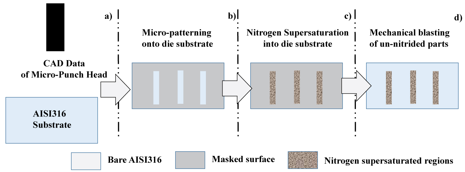
The main plasma 3D-printing process consisted of three steps as depicted in (Figure1). On the route of the screen printing for micro-patterning, two dimensional CAD model for a micro-punch head array was employed to prepare for a screen with negative micro-pattern to this model in (Figure 1a). This negative pattern was screen-printed onto the AISI316 die substrate with use of TiO2 bearing solvent ink in (Figure 1b). The spatial resolution of 10 μm in the screen printing becomes a lower bound of dimensional accuracy in this micro-patterning. A finer punch-head array is printed by the pico-second laser machining. This pico-second laser machining system utilizes the green laser with the wave length of 515 nm, the pulse duration of 8 ps, the average power of 30 W and the repetition rate of 200 kHz. Its beam spot size reaches 1 μm when using the fixed lens. The whole AISI316 die surface is once printed by TiO2 bearing ink; then, this fully masked surface was selectively cut in by the pico-second laser machining to form the tailored micro-/nano-patterns. In both micro-patterned AISI316 die substrates, their un-printed parts remain as a bare substrate surface, irrespectively of the micro-pattern widths and pitches.
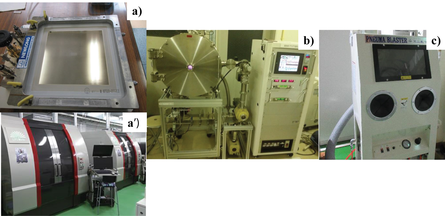
After drying this substrate at 473 K for 1.8 ks in air, these substrates were plasma nitrided at 673 K for 14.4 ks at 70 Pa under the nitrogen-hydrogen mixture gas flow with its flow rate of 160 ml/min for nitrogen to 30 ml/min for hydrogen, respectively. Since the printed pattern worked as a mask to prevent the printed parts on the substrate from nitriding, its unprinted parts were selectively nitrided as shown in (Figure 1c). After [12-14], the nitrogen solute atoms diffuse into the depth of 60 μm just below the unprinted surfaces under the above plasma nitriding conditions. The selectively nitrided layer has higher hardness than 1200 HV enough not to be mechanically blasted. Figure 1d depicts the mechanically blasted die substrate. The nitrided parts in substrate became a punch head after mechanical blasting. In the following experiments, two micro-patterning systems as well as the plasma nitriding and blasting apparatuses, were also employed as listed in (Figure 2). A screen-printer (New long, Co., Ltd.; Tokyo, Japan) was used for standard micro-patterning onto the die substrate in (Figure 2a). A pico-second machining system (LPS-Works, Co., Ltd., Tokyo, Japan) was also utilized for fine micro-patterning into the TiO2-bearing mask in (Figure 2a). High density RF (Radio-Frequency)-DC (Direct Current) plasma nitriding system (YS-Electrical Industry, Co., Ltd., Kofu, Japan) in (Figure 2b) was employed for nitrogen super saturation and diffusion into substrate. During the plasma nitriding process, the RF-voltage and DC-bias in work were controlled to be constant by 450 V and -280 V, respectively. The sand-blasting machine (Fuji-Seisakusho, Co., Ltd., Tokyo, Japan) in (Figure 2c) was utilized to selectively remove the un-nitrided parts.
Micro-embossing experiment
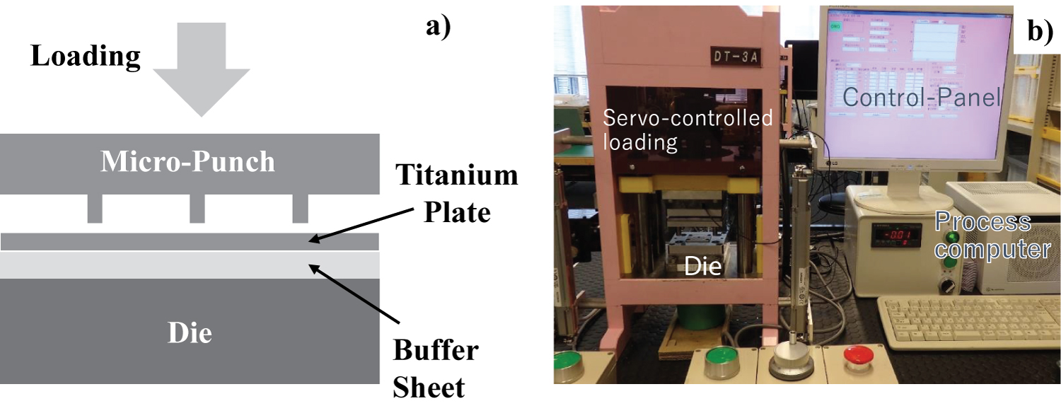
As-blasted AISI316 micro-punch was set up and fixed into the cassette dies for micro-embossing. As illustrated in Figure 3a, a pure titanium sheet with the thickness of 1 mm was employed as a work material for micro-embossing. No blank holders were used in this micro-embossing operation; a micro-punch head array was straight forwardly coined into this titanium work. (Figure 3b) shows an experimental setup where the upper and lower cassette dies are fixed into the bolsters of the CNC stamping system.
Work materials
A pure titanium plate with the thickness of 1 mm was utilized in the present study. Its chemical component was as follows, the hydrogen by 0.0012 mass%, oxygen 0.097 mass%, nitrogen 0.007 mass%, iron 0.042 mass%, carbon 0.007 mass% and titanium for balance. The average grain size (Dg) was 15 μm.
Experimental Results
Normal plasma 3D printing on the route of screen printing
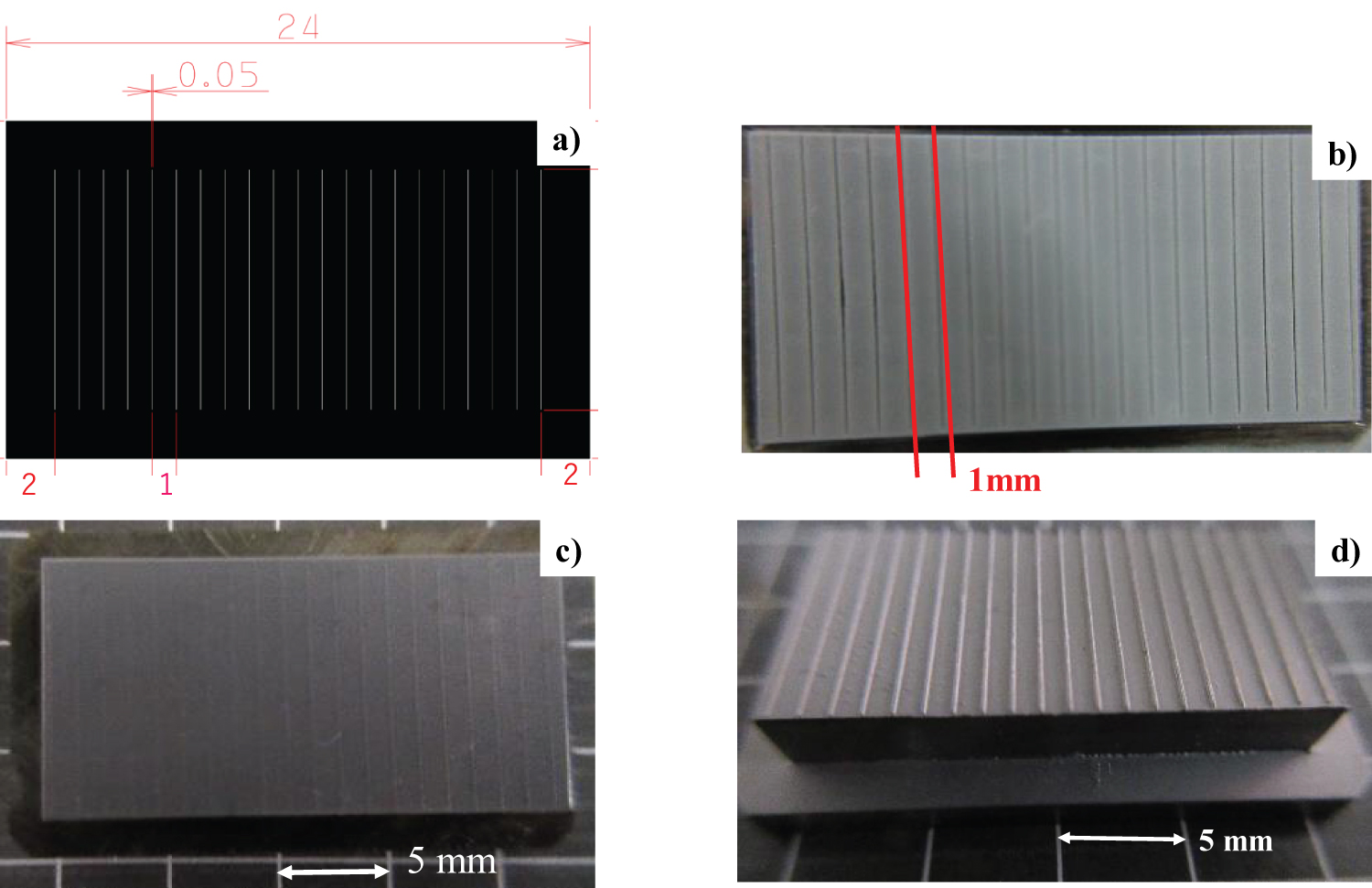
A CAD model for a micro-groove with the width of 50 μm and the length of 10 mm was used to prepare for a negative screen film to the micro-pattern with twenty micro-groove models as an array in Figure 4a. This screen was utilized to print the negative pattern onto the AISI316 die surface as depicted in Figure 4b. The spatial resolution was improved to be 5 μm less than the normal tolerance of 10 μm in screen printing. This micro-patterned AISI316 die substrate was plasma nitrided at 673 K for 14.4 ks to make selective nitrogen super saturation to unprinted parts as shown in Figure 4c. Other printed parts were not nitrided so that their hardness remains as case-hardened AISI316 hardness of 400 HV. The sand blasting was employed to mechanically remove the softer parts of nitrided AISI316 die substrate with the use of silica particles. Since the silica blasting media have hardness of 700 HV, the un-nitrided ligaments between adjacent nitrided lines with the width of 50 μm, were removed to leave a micro-punch with its twenty punch heads by the pitch of 1 mm as depicted in Figure 4d.
Figure 5a depicts the finished micro-punch with twenty punch-heads. Every punch head has the average width of 50 μm and height of 125 μm as shown in Figure 5b. This Figure 5b proves that every border line between the nitrided and un-nitrided zones before blasting turns to be a side surface of punches with the steep gradient in height. The whole micro-punch heads are scribed into the original AISI316 die substrate by this standard plasma 3D-printing. In case of mechanical milling and laser micro-machining processes, the cutting paths to shape out a single punch head must be built up by twenty times in preparation of CAM (computer aided machining) data and the whole take time for machining increases twenty times at least.
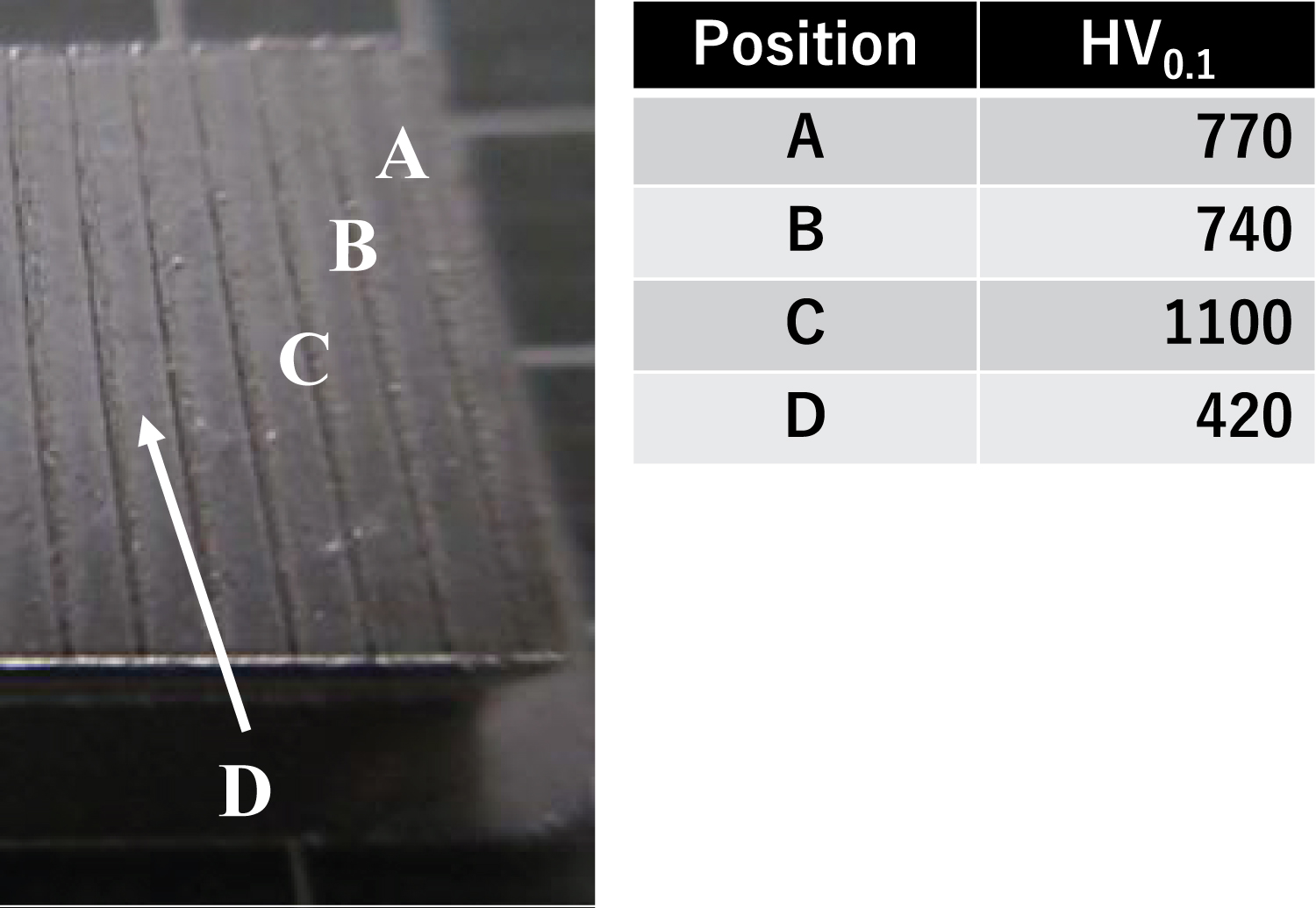
Micro-Vickers hardness testing was employed to measure the point wise hardness by the weight of 0.1 kg. The indenter tip had a curvature radius of 5 μm enough to measure the hardness even on the punch heads. Four points were selected for this measurement; Figure 6 shows the average hardness of five measured values on the three punch heads and on the ligament between two adjacent heads. The hardness at the heads-A and -B is the lowest among twenty punch heads and a little higher than the shooting medium hardness of 700 HV. The hardness 1100 HV at the head-C is representative to the average hardness of other punch heads. On the other hand, the ligament between two adjacent heads remains to have the same hardness 420 HV as the case-hardened AISI316 die. This explains that the hardness profile with hardened heads and un-hardened ligaments by the plasma nitriding turns to be a cross-sectional profile of micro-punch with multi-heads after blasting.
Normal micro-embossing into titanium plate
The above micro-punch was inserted into the cassette die for embossing into a pure titanium sheet. Figure 7a depicts the embossed titanium sheet at the maximum stroke of 160 μm from the first contact position of micro-punch heads to work. Corresponding to twenty micro-heads in Figure 5a, twenty micro-grooves are coined into the work. Three dimensional profile meter (Keyence; Tokyo, Japan) was employed to measure the three dimensional configuration of this micro-groove. Figure 7b shows the depth profile of micro-groove. This microgroove depth (d) reaches 52 μm; its bottom width (WB) is 50 μm. The inlet width (Winlet) of micro-groove is around 200 μm, more than the punch head width of 50 μm. This implies that the top of titanium sheet flows into the cavity together with formation of side surfaces in the micro-groove at the absence of blank holders in this micro-embossing. No surface roughing took place at the side walls and bottom surfaces of microgrooves. The average surface roughness of free plate remained to be 1 μm.
Plasma 3D printing on the route of pico-second laser processing
The pico-second laser machining was employed to cut the micro-patterns into the TiO2-bearing mask surface on the AISI316. As shown in Figure 8a, each positive line-pattern with the width of 10 μm was cut into the printed mask on the substrate. Other mask surfaces remain the same as before Figure 8b shows the plasma nitrided substrate at 673 K for 14.4 ks. Ten line-patterns on the AISI316 substrate are selectively nitrided by masking technique. After sand-blasting, the other parts than these ten line patterns were mechanically removed by sand-blasting for 600s. Figure 8c depicts the as-blasted micro-punch with the width of 10 μm. In the micro-patterning by the screen printing, its dimensional accuracy is pre determined by the tolerance of 10 μm in fabrication of a screen film. On the other hand, this pico-second laser micro-machining has finer resolution in space down to 1 μm. Hence, a micro-punch with the narrower head width can be made by this micro-patterning.
Figure 9a shows the line-pattern with the width of 5 μm by this fine plasma 3D-printing. No essential difference in the micro-patterning behavior by the pico-second laser processing is seen in comparison between Figures 8a and Figure 9a. As shown in Figure 9b, ten micro-line patterned AISI316 was selectively nitrided to harden these lines. After sand-blasting, a micro-punch with the punch head width of 5 μm is also built up to have the height of 100 μm, as shown in Figure 9c.
Fine micro-embossing into titanium plate
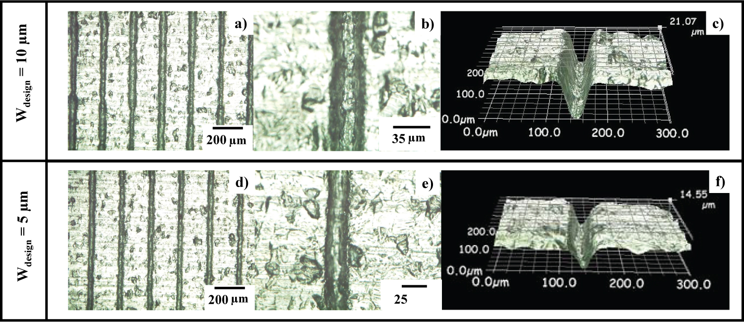
Two micro-punches with ten head array were fixed into the cassette die in the similar procedure as stated in 3.2. No essential changes in the procedure of micro-embossing were utilized in the following experiments. Figure 10 compares the micro-grooves coined into the pure titanium sheet by using these micro-punches. In the similar manner to Figure 7, the micro-groove arrays with the bottom widths of 10 μm and 5 μm are cut into the titanium sheet, respectively. Under the same maximum stroke of 160 μm as shown in Figure 7, the micro-groove depth monotonously decreases with the punch width (W); e.g., d = 52 μm for W = 50 μm, d = 21 μm for W = 10 μm and d = 15 μm for W = 5 μm, respectively. This reduction of d with decreasing W reveals that the frictional stress against the applied force in micro-embossing is enhanced by the grain size effect. When W (= 50 mm) > Dg, the frictional stress at the punch edge is evaluated by the shear yield stress of titanium. When W < Dg, a micro-plastic flow is induced in a specified grain and followed by the shearing flow at the vicinity of punch head. In particular, a single crystal with Dg > W experiences the significant change in plastic velocity from the transgranular micro-plastic flow along the easiest crystallographic orientation in the grain to the plastic flow around the punch edge corner [16]. This grain size effect on the local plastic flow at the micro-punch edge, enhances the shear resistance against the applied load and shortens the embossed depth even under the same stroke.
This size dependence of metal forming tools against the grain size of metals characterizes the micro-metal forming [17]. In particular, the surface roughness of work materials is enhanced by micro-forming through the micro-plastic flow in each grain. Comparing the surface conditions of micro-embossed titanium sheets in (Figures 7 and Figure 10) the surface roughness is much enhanced with reduction of the punch width. This proves that micro-embossing process into titanium sheet by using the micro-punch with its head width less than its grain size is significantly influenced by the size effect in micro-plastic flow.
Discussion
Different from the mechanical milling or the laser micro-machining, the dimensional accuracy of micro-punch head in the plasma 3D-printing is mainly governed by the spatial resolution in micro-pattering. When using the screen printer, the micro-punch width is limited by the dimensional tolerance of 10 μm. The pico-second laser micro-machining with the spatial resolution of 1 μm must be used to fabricate the micro-punches with finer head width than 10 μm. The height of micro-punches is determined by the nitrided layer thickness (DN) as well as the duration time in mechanical blasting (τb). DN reaches to 60 μm in the present plasma nitriding conditions and τb is constant by 600 s. As shown in Figure 5, Figure 8 and Figure 9, the punch height reaches 100 to 125 μm, higher than DN. Since the un-nitrided parts of micro-punches are removed by blasting, the borders between nitrided and un-nitrided zones turn to be steep and straight side-surfaces of punches. No erosion is detected on these side surfaces even after sand-blasting of un-nitrided die materials in depth. The micro-punch height (D) is mainly determined by τb.
After analyses in [18], this micro-punch head with D > DN has a layered micro structure. It consists of the fine-grained, two-phase AISI316 homogeneous microstructure in the lower depth than DN and the heterogeneously nitrided AISI316 matrix in the deeper layer than DN. The average grain size of homogeneously nitrided layer was refined from the normal size of 10 μm in the AISI316 substrate to 0.1 μm. The original austenitic phase changed to a two-phase with fine distribution of austenitic and martensitic phases. This microstructure evolution advanced homogeneously into the depth of AISI316 die substrate together with nitrogen solute atom diffusion. On the other hand, AISI316 matrix below the nitriding front end around D = DN had heterogeneous microstructure, where the average grain size was nearly the same as matrix. Hence, micro-punches with W = 50 μm, 10 μm and 5 μm, have two-layered system where the top layer has finer grain size of 0.1 μm and higher hardness than 1100 HV and the bottom one has heterogeneously nitrided AISI316 matrix with nearly the same grain size as original AISI316.
In addition to monotonous reduction of d with decreasing W, the grain size effect on drooping is also observed in this micro-embossing. Figures 7 and Figure 10 shows that WB is just corresponding to the head with of micro-punches; e.g., WB = 50 μm for W = 50 μm in Figure 7, and WB = 10 μm for W = 10 μm and WB ~ 4 to 6 μm for W = 5 μm in (Figure 10). This implies that shearing and bending deformation takes place at the vicinity of punch edges in the absence of blank holder in the present experiments. After recent studies on the micro-embossing of austenitic stainless steels [19,20], the work materials droop and bend to broaden Winlet together with shearing. With sharpening the micro-punch edge, or, with plastic strain concentration at the micro-punch edge, ∆W = (Winlet - WB)/2 narrows to a minimum droop. Then, this ∆W becomes a parameter to describe the effect of punch width on the plastic strain concentration. Winlet = 200 μm and ∆W = 75 μm when embossing by the micro-punch with W = 50 μm in (Figure 7). Winlet = 30 μm and ∆W = 10 μm for W = 10 μm, and, Winlet = 15 μm and ∆W = 5 μm for W = 5 μm, in Figure 10. This monotonous reduction of ∆W with decreasing W comes from the plastic strain concentration at the vicinity of micro-punch edges. When embossing by the micro-punch with W = 50 μm, the work materials are bent to form the micro-groove by low plastic concentration and to enlarge Winlet. With decreasing W, the plastic flow of work materials is limited to the vicinity of micro-punch.
Let us estimate the take time for fabrication of the micro-punch with 100 punch heads for W = 5 μm, D = 100 μm, L = 10 mm and the pitch of 0.2 mm. In case of micro-milling, the machining speed, the cutting distance and the threading depth are assumed to be 1 mm/s, 5 μm and 5 μm/path. The total length per a path to be cut is estimated to be 40,000 mm. Number of cutting paths is 100 μm /5 mm/path = 20 paths. The total takt time is counted by 40,000 mm × 20/1 mm/s = 800 ks only for actual machining without failure of cutting tools. In the present plasma 3D-printing, the micro-patterning with use of the laser machining needs 10s × 100 = 1 ks, and, the nitriding requires for 21.6 ks including heating and cooling processes. The sand-blasting needs 600s. Then, total takt time is estimated by 23.2 ks. This significant reduction of total takt time proves that plasma 3D-printing provides more efficient tool to build up the multi-head micro-punch array.
As discussed in [1,3-5], the biomedical titanium parts and tools have complex shapes in geometry and topology with bioactive surfaces by micro-/nano-textures. In most of them, their size ranges from submicron to 10 μm and their aspect ratio is higher than 2.0. Under these dimensional conditions, the plasma 3D-printing enables to duplicate the tailored micro-/nano-textures onto the product surfaces by micro-embossing the micro-/nano-textured dies. In particular, the height-to-width of micro-punch is controllable by the blasting time, and, more depth-to-width of embossed micro-groove than 3~5 is also attained by the present fine stamping with use of micro-punch array. Furthermore, the geometric regularity of the micro-embossed micro-grooves in titanium plate proves the reliability of present method for micro-/nano-texturing to form the bioactive titanium product surfaces.
Conclusion
The plasma 3D-printing becomes an adaptive tool to fabricate various micro-punches even with arrayed punch heads for micro-embossing processes. The screen printing is suitable to draw the micro-pattern with each head width of 50 μm for this plasma 3D-printing. As-blasted micro-punch with twenty heads is directly utilized to coin an array of micro-grooves with the width of 50 μm, the depth of 120 μm and the pitch of 1 mm. This screen printing is exchanged with the picosecond laser machining to cut the micro-patterns into the TiO2 bearing mask on the die substrate. Without essential change of the plasma 3D-printing procedure, the micro-punches with their head width of 10 μm and 5 μm are built up with nearly the same accuracy in dimension. This plasma 3D-priting provides a tool to fabricate a micro-punch with more complex network of heads without increase of takt time.
These micro-punches are utilized for embossing the micro-groove array into the titanium sheet. The punch head condition is transcribed to a micro-groove bottom surface with the same width as head. Each microgroove in the array has steep gradient side surfaces; it is useful to trap the targeting cells or bacteria for biomedical treatment and to make antibacterial surface decoration.
Acknowledgement
The authors would like to express their gratitude to Mr. S. Kurozumi (Nano-Film Coat, llc.) and Mr. T. Tamura (Tamurajia, Co., Ltd.) for their help in fine stamping, finishing and buffing.
References
- Rack HJ, Qazi JI (2006) Titanium alloys for biomedical applications. Mater Sci Eng 26: 1269-1277.
- Niinomi M (1998) Mechanical properties of biomedical titanium alloys. Mater Sci Eng: A 243: 231-236.
- Zhu J, Zeng Q, Fu T, (2019) An updated review on TiNi alloy for biomedical applications. Corrosion Reviews 37: 104-110.
- Zhou L, Lai Y, Huang W, (2015) Bio-functionalization of microgroove titanium surfaces with an antimicrobial peptide to enhance their bactericidal activity and cytocompatibility. Colloids and Surfaces B: Biointerfaces 128: 552-560.
- Zhang LC, Chen LY (2019) A review on biomedical titanium alloys: Recent progress and prospect. Advanced Eng Mater 21: 1-29.
- Jang Y, Choi WT, Johnson CT, et al. (2018) Inhibition of bacterial adhesion on nanotextured stainless steel 316L by electrochemical etching. ACS Biomater Sci Eng 4: 90-97.
- Ferraris S, Cochis A, Cazzola M, et al. (2019) Cytocompatible and anti-bacterial adhesion nanotextured titanium oxide layer on titanium surfaces for dental and orthopedic implants. Front Bioeng Biotechnol 7: 103-110.
- Schmid K (2008) Manufacturing Processes for Engineering Materials. (5th edn), Prentice Hall New Jersey.
- Karino K (2011) Machining and milling of die materials. Nikkan-Kogyo-Shinbun.
- Aizawa T, Inohara T (2019) Pico- and femtosecond laser micromachining for surface texturing. In: Micromachining Intech Open: London, UK, 1-24.
- Aizawa T, Shiratori T, Kira Y, et al. (2020) Simultaneous nano-texturing onto a CVD-diamond coated piercing punch with femtosecond laser trimming. J Applied Sciences 10: 1-12.
- Aizawa T (2018) Micro-manufacturing by controlled plasma technologies. J Automotive Technology 72: 35-41.
- Shiratori T, Aizawa T, Saito Y, et al. (2019) Plasma printing of an AISI316 micro-meshing punch array for micro-embossing onto copper plates. J Metals 9: 1-11.
- Aizawa T, Shiratori T, Wasa K (2019) Plasma-printed AISI316L multi-punch array for fabrication of aluminum heat sink with micro-pillar fins. Proc 3rd, Raleigh, NC, USA, 220-223.
- Aizawa T, Saito Y, Hasegawa H, et al. (2020) Fabrication of optimally micro-textured copper substrates by plasma printing for plastic mold packaging. Int J Automation Technology 14: 200-207.
- Ide N, Hayakawa K, Asano S (2001) Evaluation of microplastic flow stress in copper alloys from amplitude-dependent internal friction. Mater Trans 42: 435-438.
- Manabe KI (2020) Metal micro-forming. Metals MDPI 10: 1-3.
- Aizawa T (2018) Low temperature plasma nitriding of austenitic stainless steels. Stainless Steels and Alloys, Intech Open 31-50.
- Shiratori T, Yoshino T, Suzuki Y, et al. (2019) Deformation of transformation characteristics in micro-punching of stainless steel AISI304, Proc 3rd WCMNM, Raleigh, NC, USA, 130-133.
- Aizawa T, Shiratori T, Komatsu T (2020) Integrated manufacturing of fine-grained stainless steels for industries and medicals. In: Engineering Steels and High Entropy-Alloys, IntechOPen, London, UK, 3-26.
Corresponding Author
T Aizawa, Surface Engineering Design Laboratory, SIT 3-15-10 Minami-Rokugo, Ota-City, Tokyo, 144-0045, Japan.
Copyright
© 2020 Aizawa T, et al. This is an open-access article distributed under the terms of the Creative Commons Attribution License, which permits unrestricted use, distribution, and reproduction in any medium, provided the original author and source are credited.

